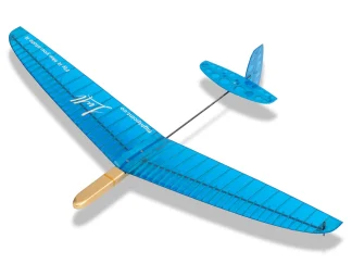
The glider has an outstanding flying envelope that allows pilots to handle a low-level lift and strong winds with confidence.
For better convenience, the ballast tubes are located in the wings and provide a fast way to change the glider settings at the field.
The wingspan is only 2.5 meters, which lets pilots hunt for low-level thermals, just like with the 4-meter ships.
You can purchase this model as a kit and build it on your own or choose a Receiver Ready option and let our professional team build it to your preference – with servos and powertrain.
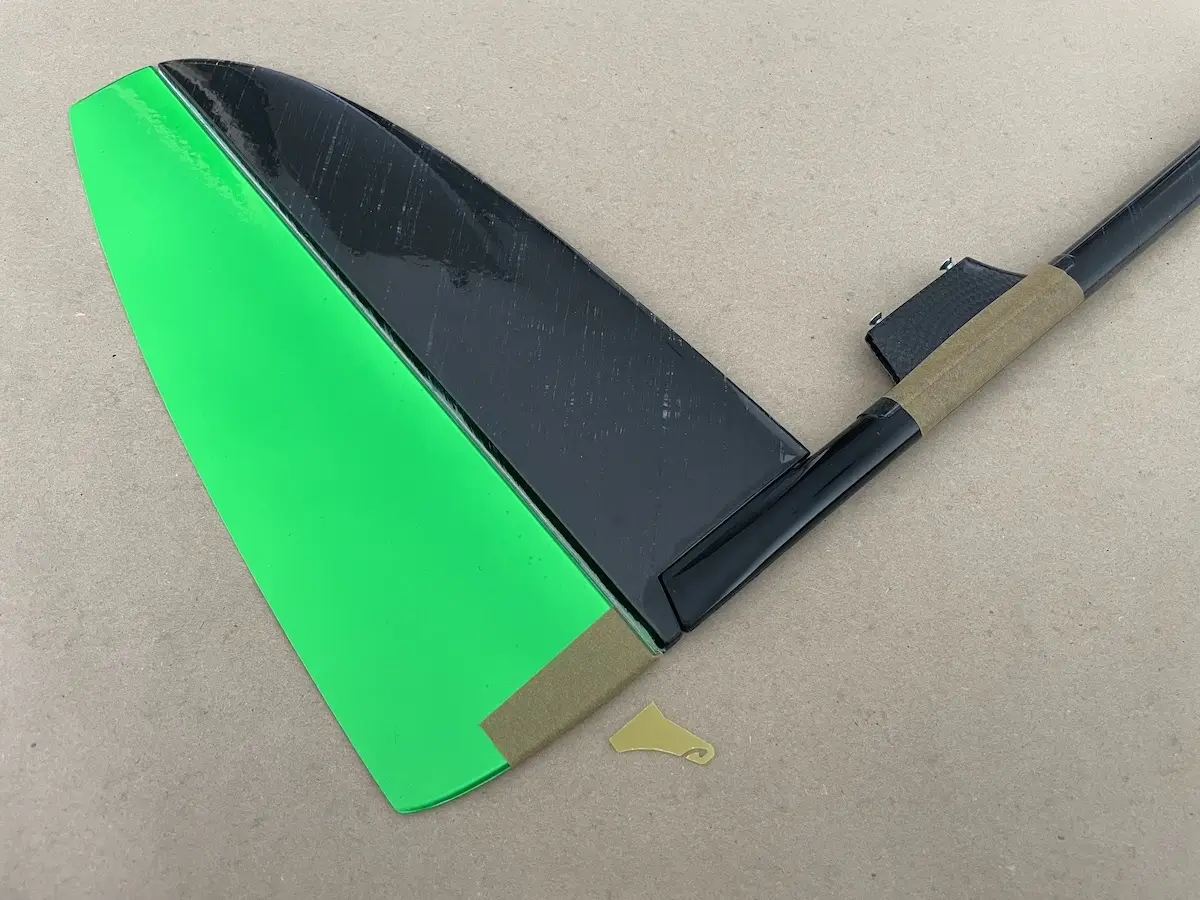
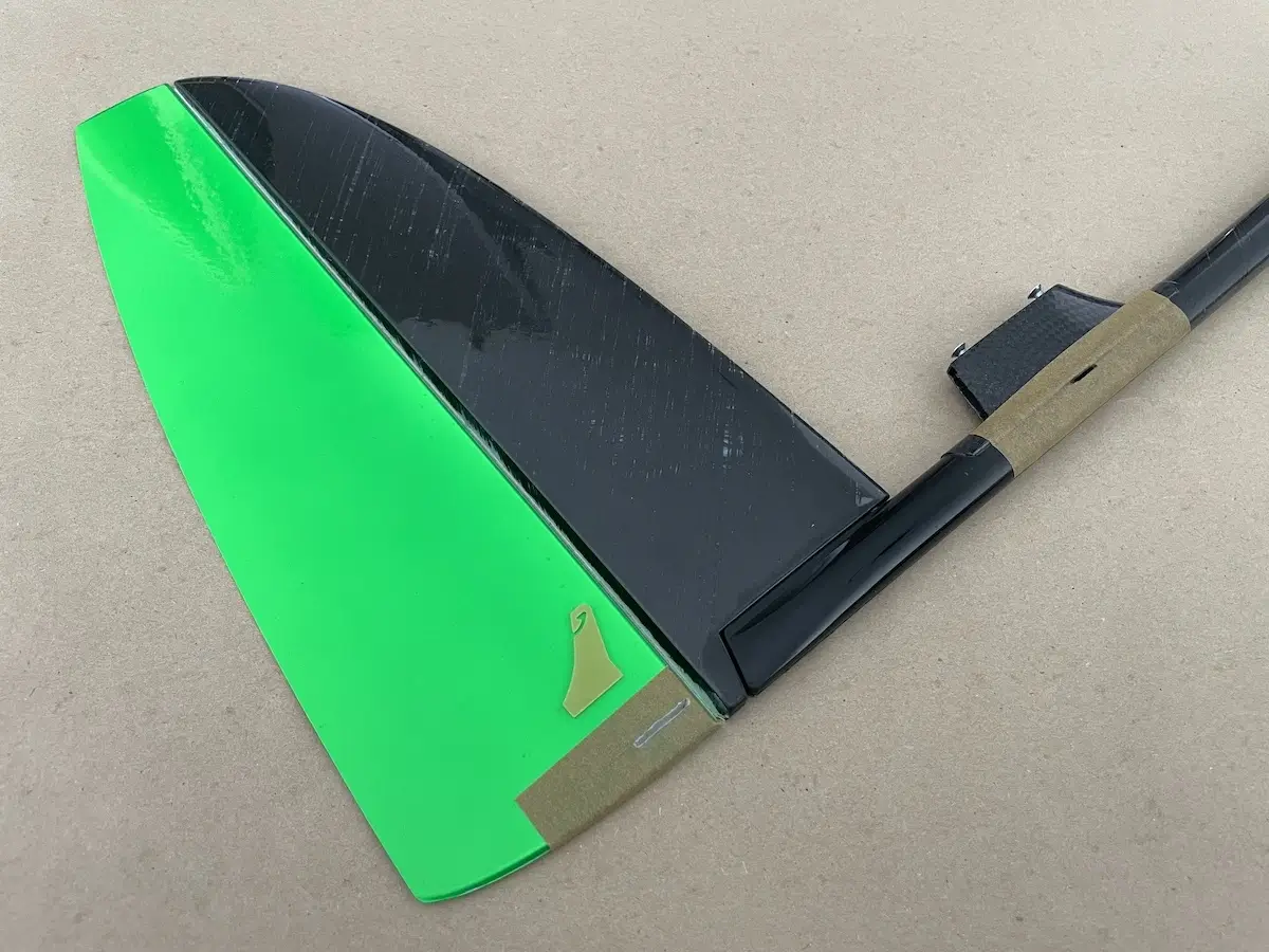
If you prefer to build it on your own, please, refer to the images below.
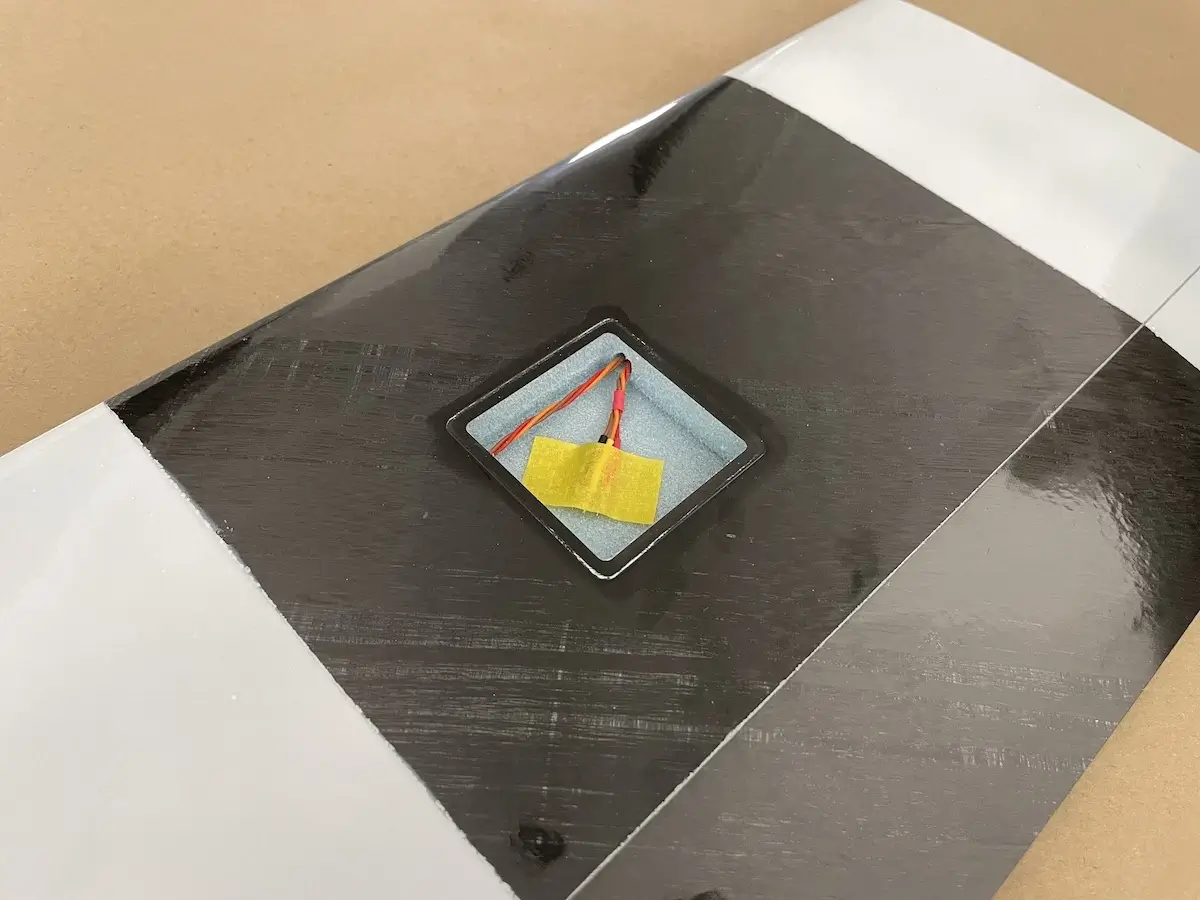
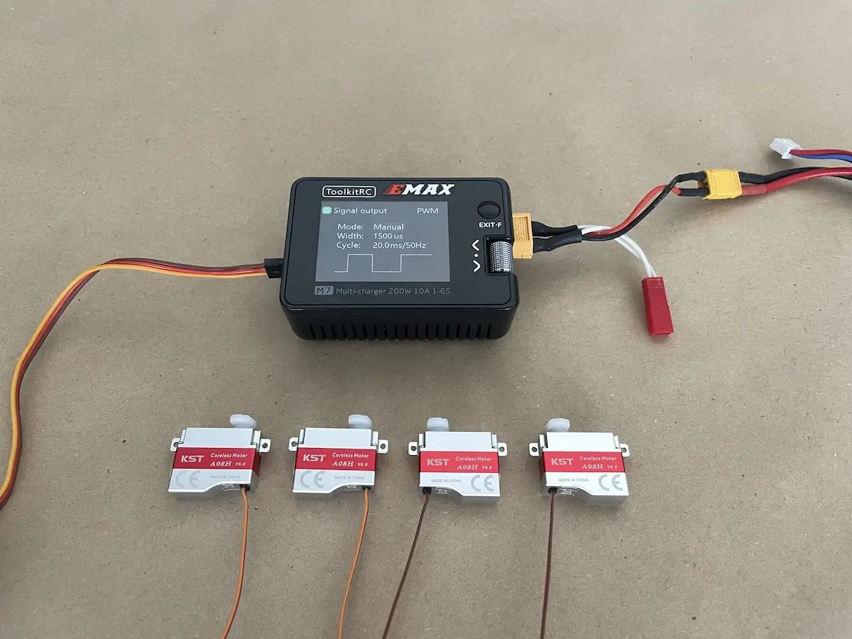
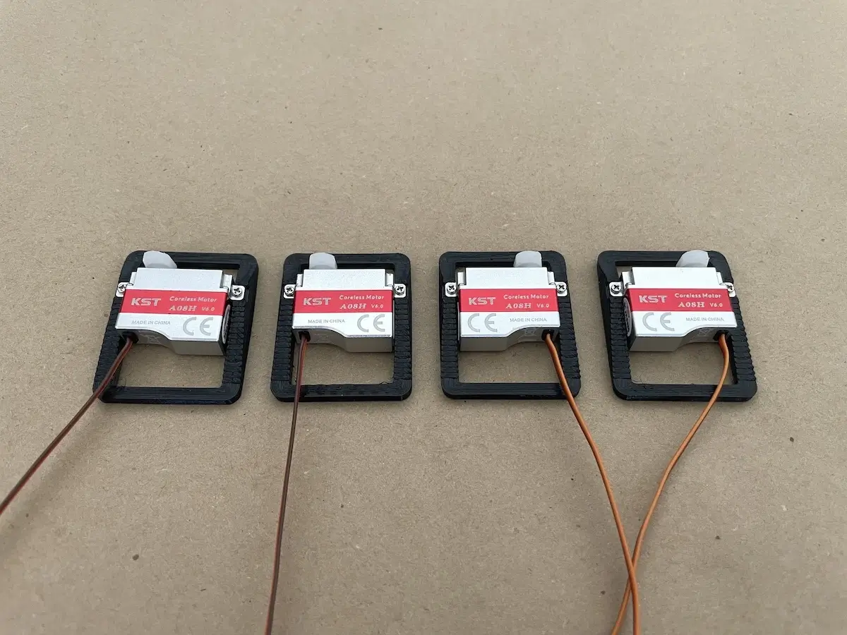
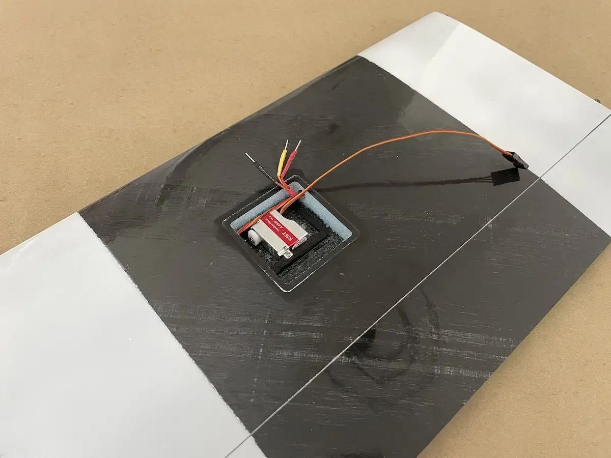
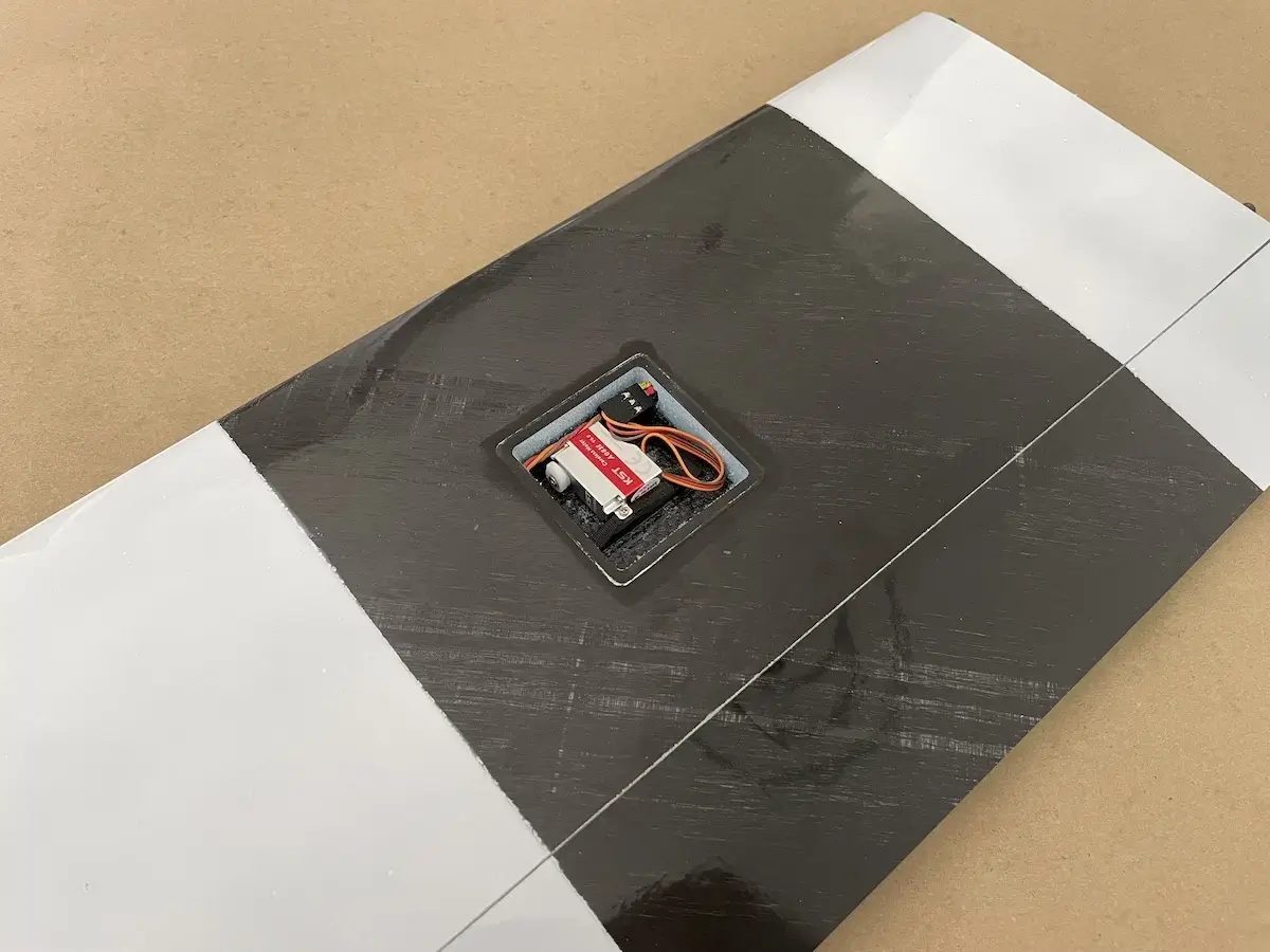
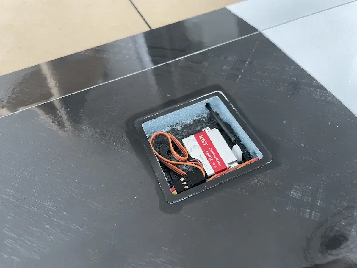
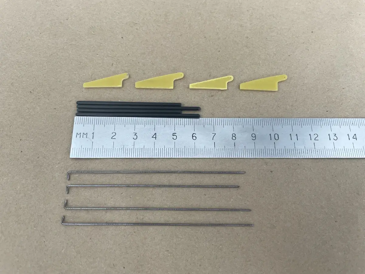
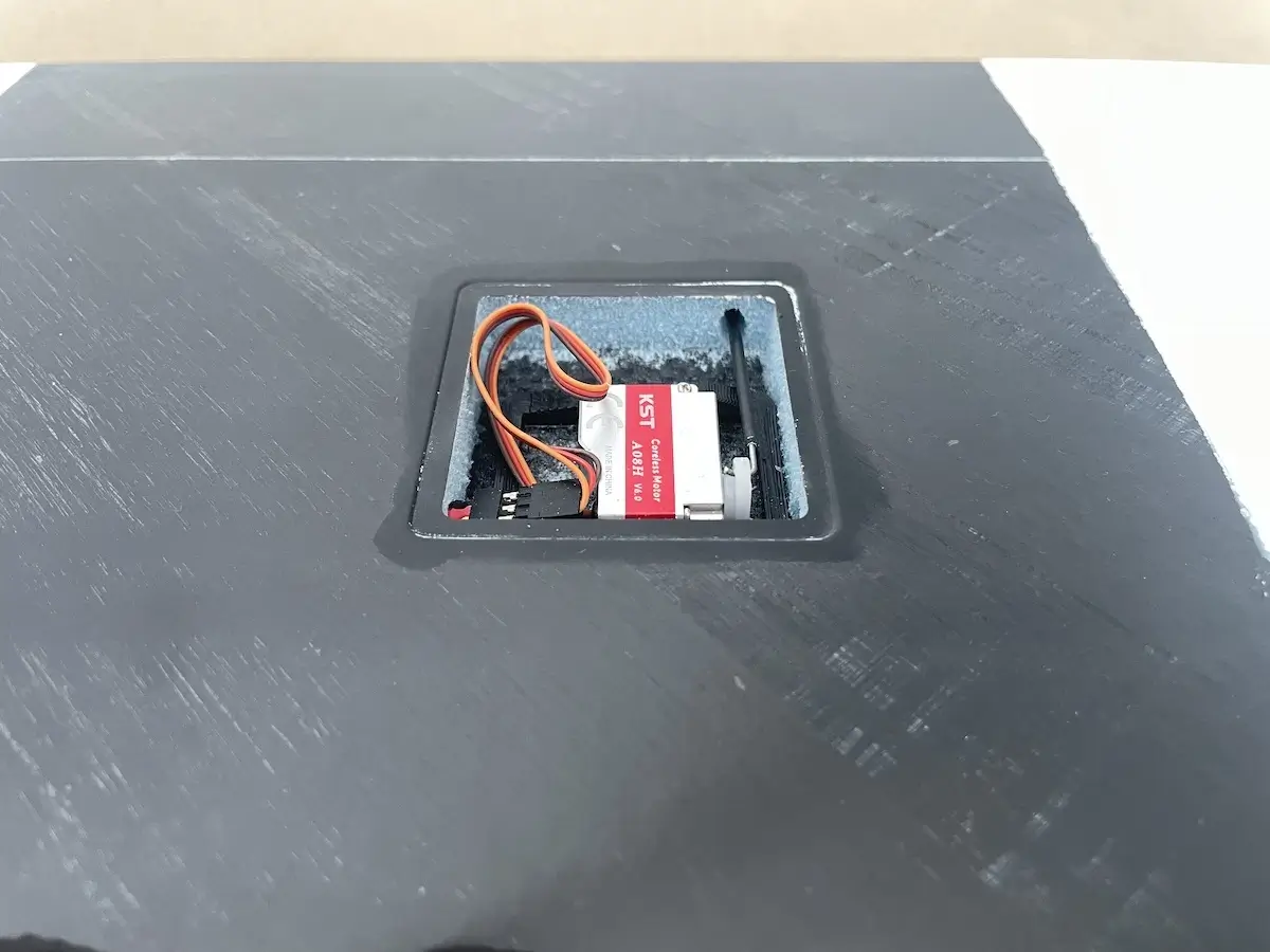
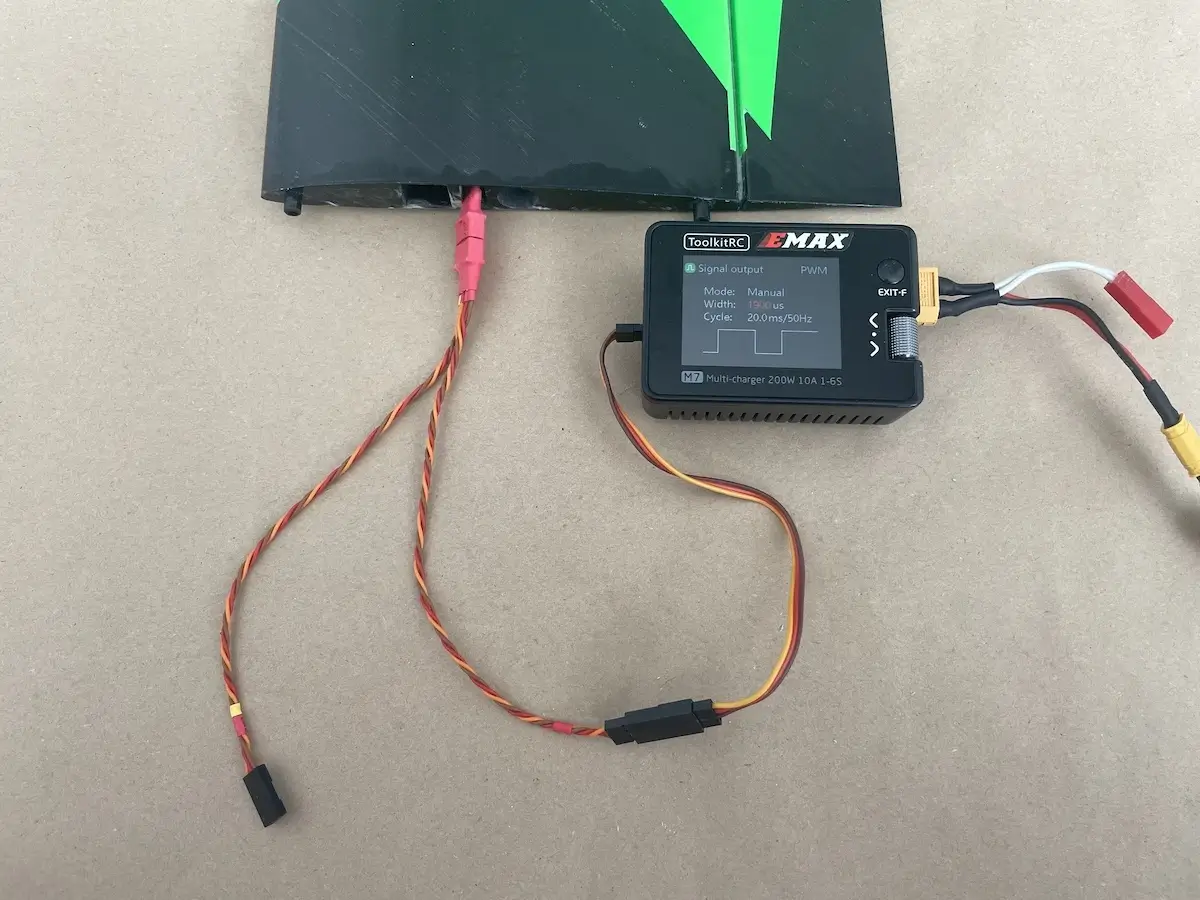
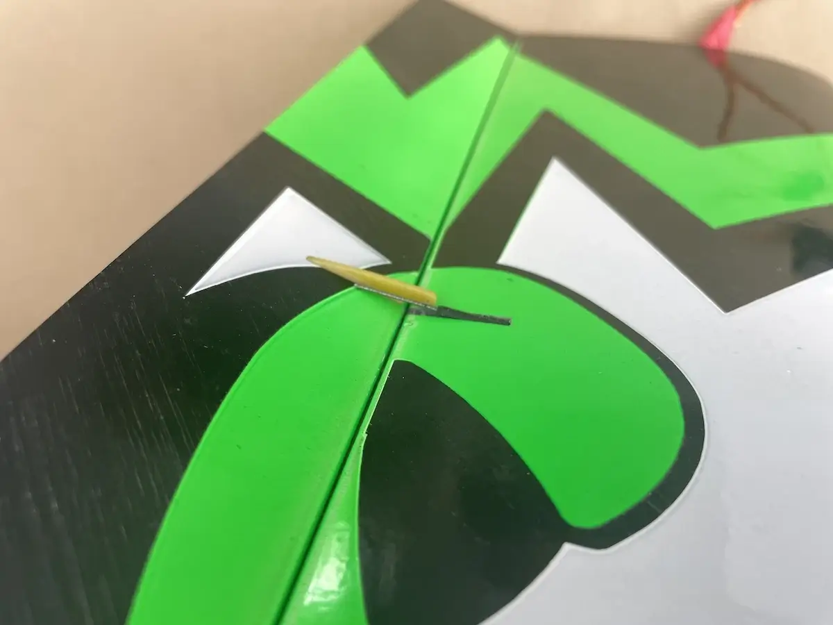
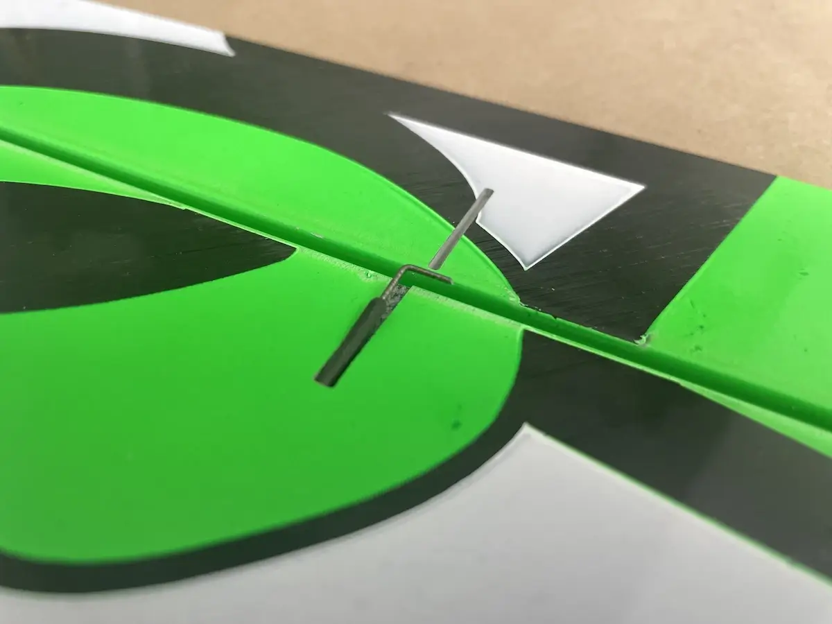
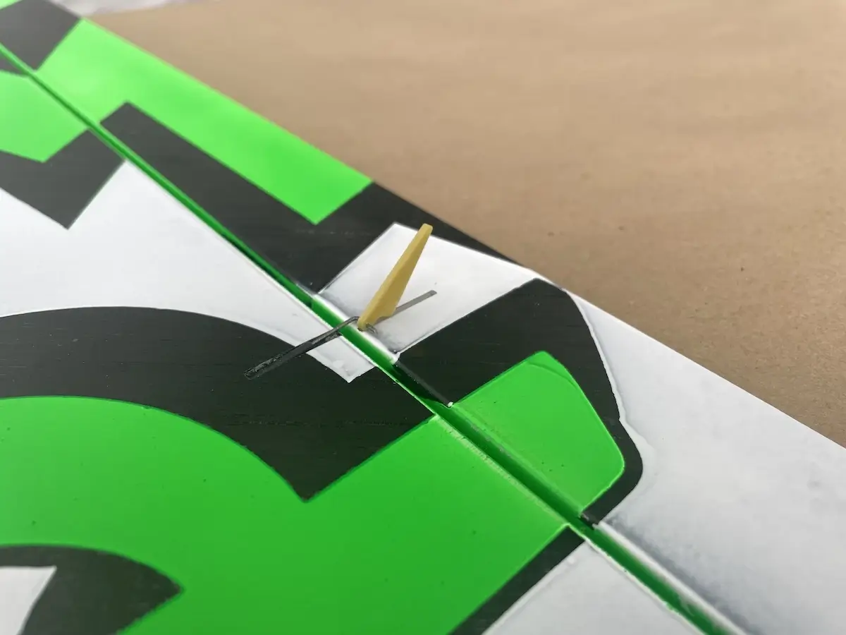
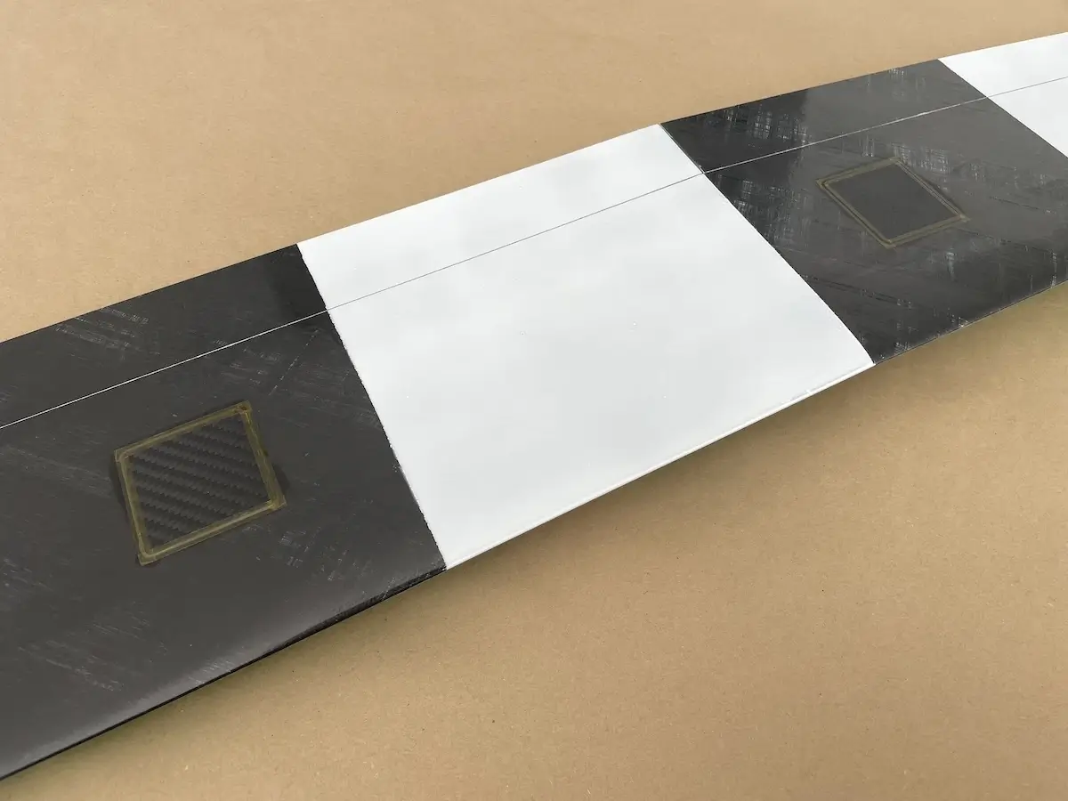
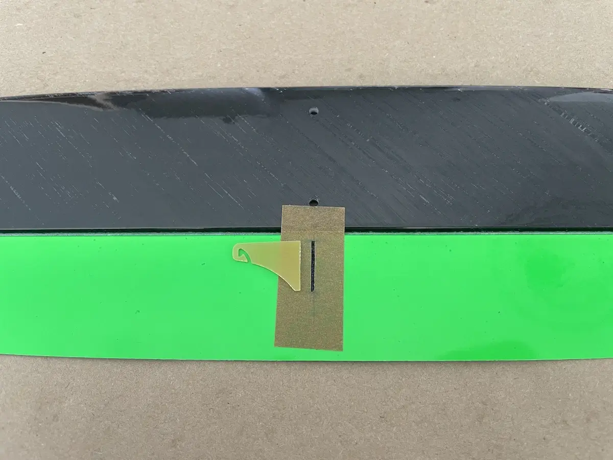
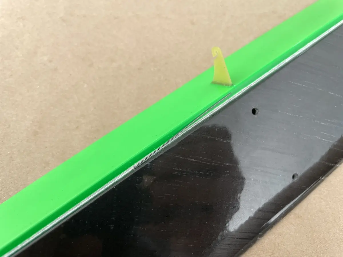
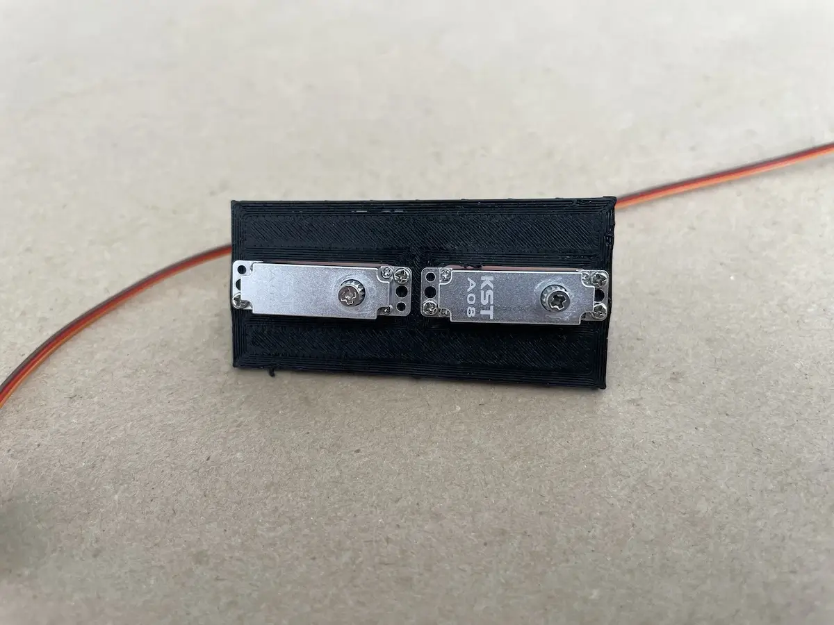
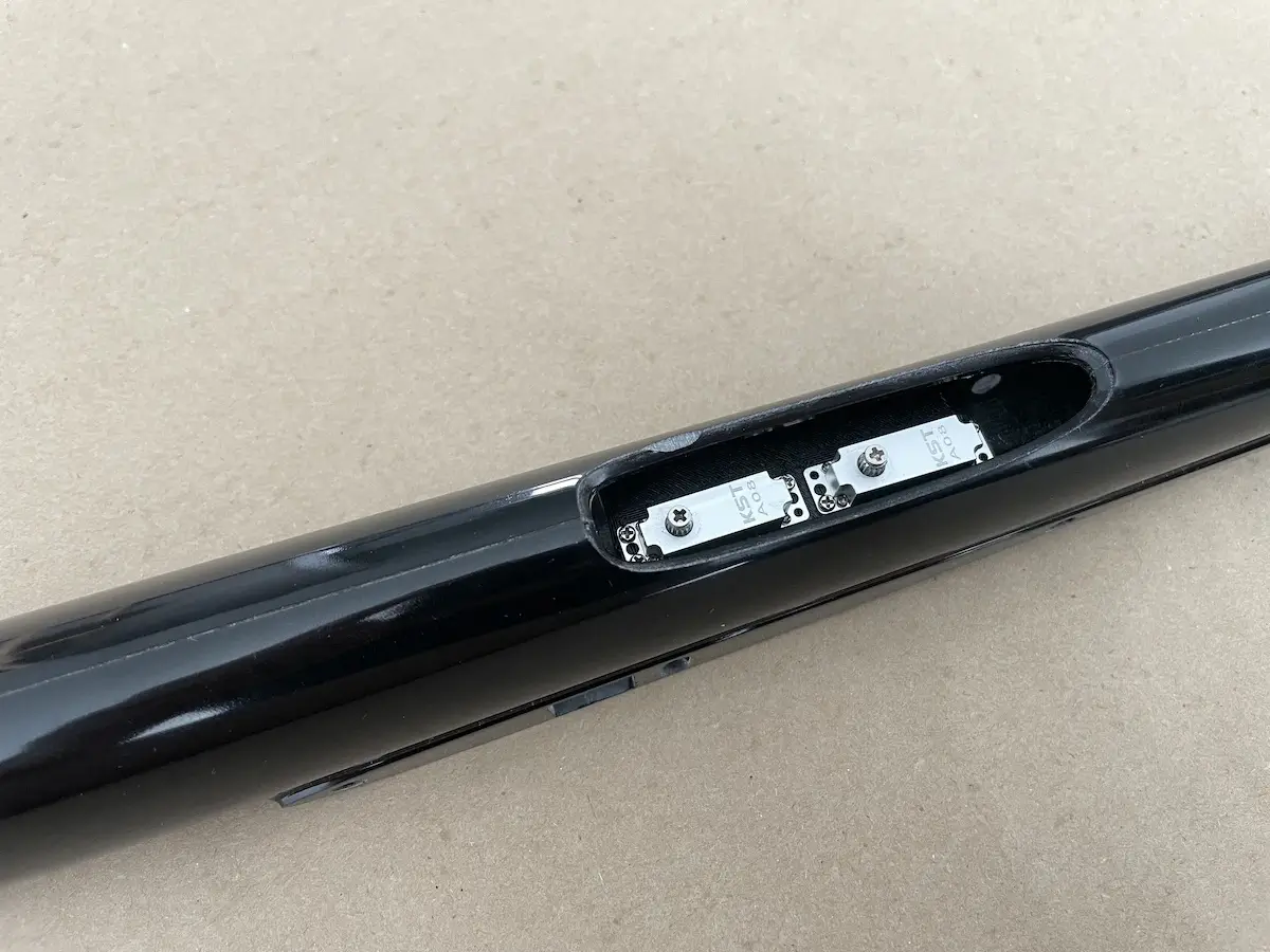
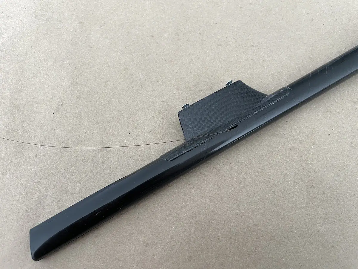
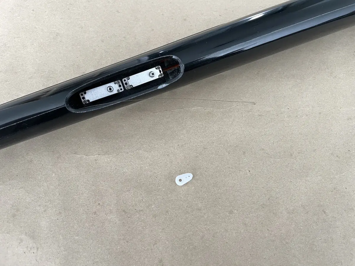
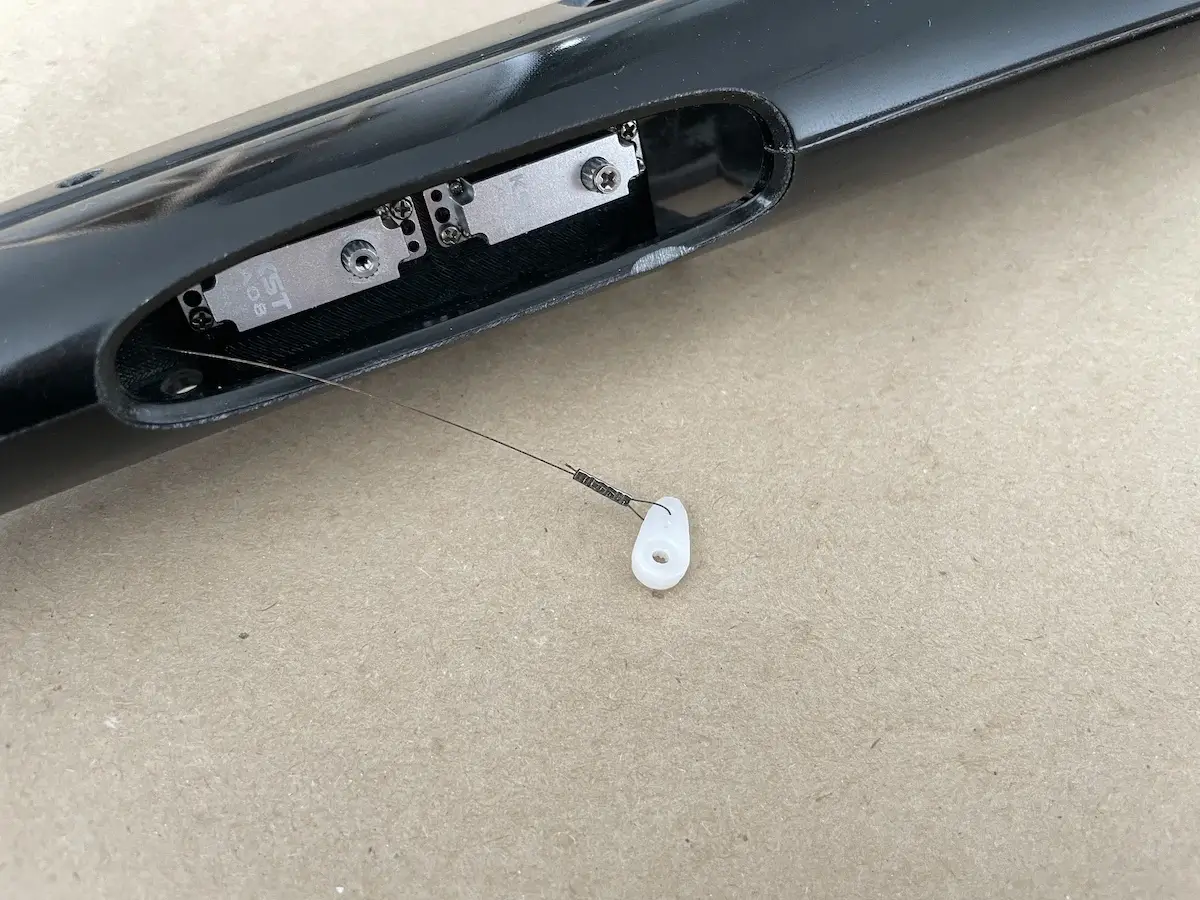
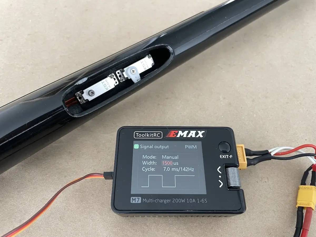
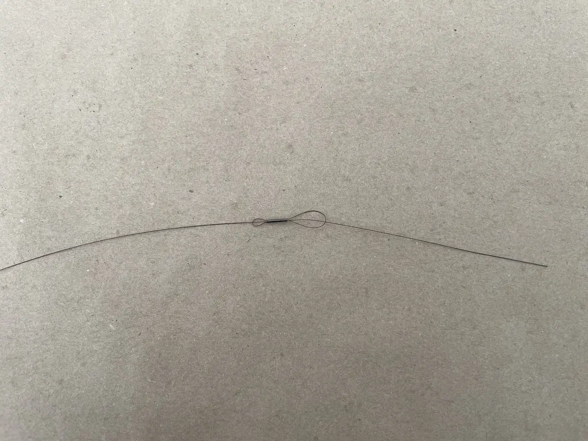
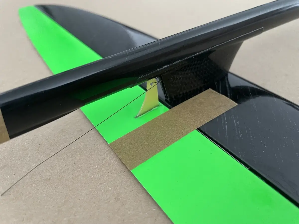
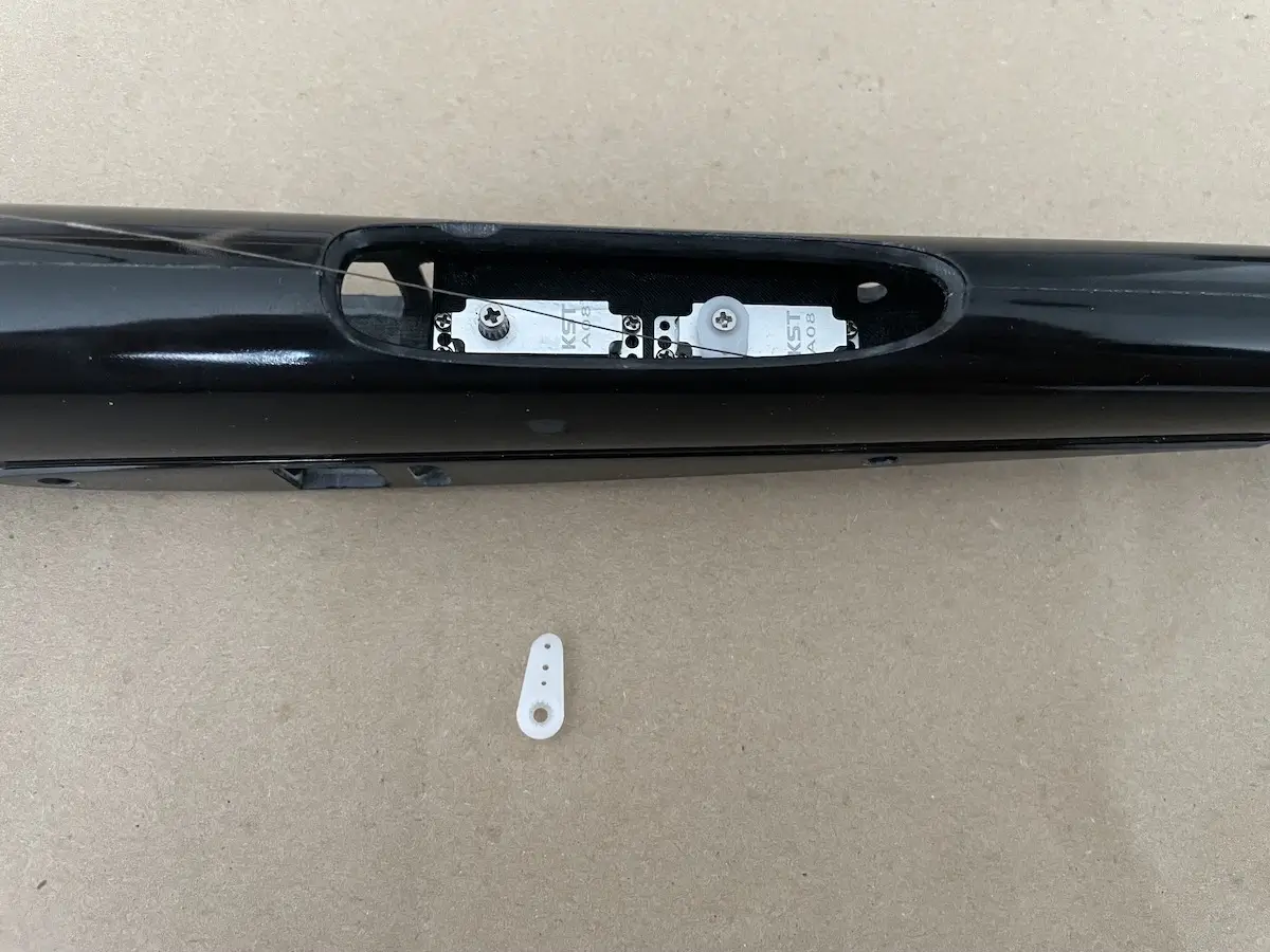
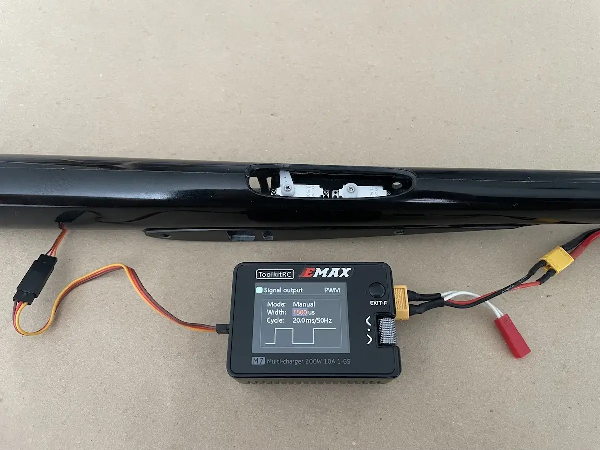
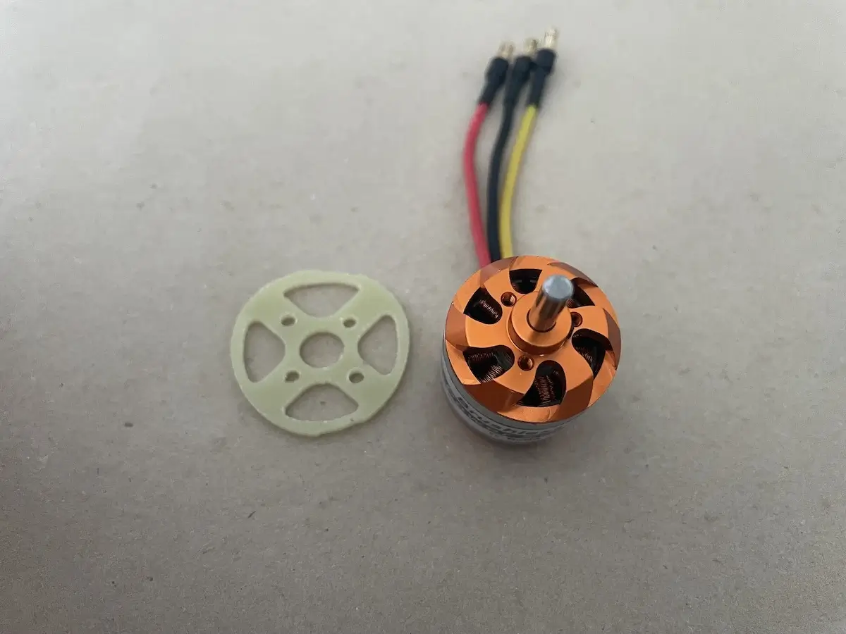
The wing harness comes pre-installed in the wingsRemove the foam from the servo openings to get the naked carbon skinCenter the servos, trim and install the servo arms. For ailerons, you might want to make a hole as close to the shaft as possible.Install your servos in framesGlue the frames into the wings Connect your servos, double-check polarity of the wiresMake a pushrod channel with a provided 2x1mm CF tubeMake sure the CF tube moves freely inside the channel and have some extra vertical gapPrepare the pushrod wires, cut 2x1mm CF tube, and prepare your Conrol hornsPut the pushrod wire into 2×1 CF sleeve Connect your servo to a servo tester with a provided harness and dry-fit your control hornsSet Flap servos to Full-Up, move your Flap accordingly, and mark the place where you need to make an L-band. Center the Aileron servo and flatten the control surface with the wing bottom for Ailerons.Make your L-Bands Install control horns onto the L-bands and clue the last in placePut a drop of CA on the link to remove any possible slopRepeat for all wing control surfacesLaslty, install the servo coversFind an Elevator control hornMask, mark and cut the opening for the control horn in the elevatorClue the horn in place and install the torsion springMask the Rudder and the boom where the cable opening will beMake an openings with the sharp knife. The rotary tool with diamond bit/disc will come in handy as wellClue the Rudder horn in placeInstall TWO torsion springs into the rudder to prevent flattering in high speedsPrepare fuselage servos and a servo frameInstall your servosPosition the servo plate inside the fuselate, as close to the “top” of the fuselage as possiblePush the cable through the opening in the boomTrim and the Rudder servo armCrimp the cable on the servo armCenter the Rudder (rear) servo and install the servo arm on the servo shaftCenter your Rudder make a nice tension on the cable and crimp it with a provided tubeCreate a loop with a pigtail for the Elevator pull-cableInstall the Elevator and hook up the pull cableTrim the elevator servo arm, you’ll need a long one to have a good deflectionCenter the Elevator (front) servo and install the servo arm. Make nice tension on the cable and crimp it with pliersPrepare your motor and firewallPut the both parts into the fuse separately and attach the firewall onto the motor once inside. Pay attention to the fuselage seam location and as well as the corresponding spots on the firewall.Position the motor inside, install your spinner w/ prop, fix it in place and glue the firewall in.
Pro Tip: Put an O-Ring over the main hatch to prevent losing it
Under certain circumstances, like high-speed maneuvers, the main hatch cover may become loose in flight and fall off.
Of course, this isn’t something that you would enjoy…
So, we recommend securing this hatch in any way that you feel convenient. From our experience, the reusable O-Ring is one of the most effective ways that costs nothing, is lightweight, not draggy, and can be done at the field in a few moments.
Please, check the following video that explains this process.
Once done, you’ll be ready to install your Rx and battery and start with the radio setup.
Joy F5J Setup Tips
For FrSky or OpenTX / EdgeTX users, we recommend the SoarOTX F5J template for radio setup.
It is free and extremely easy to use.
Additionally, it provides a flight scoring system that will come in handy during training or simple timekeeping.
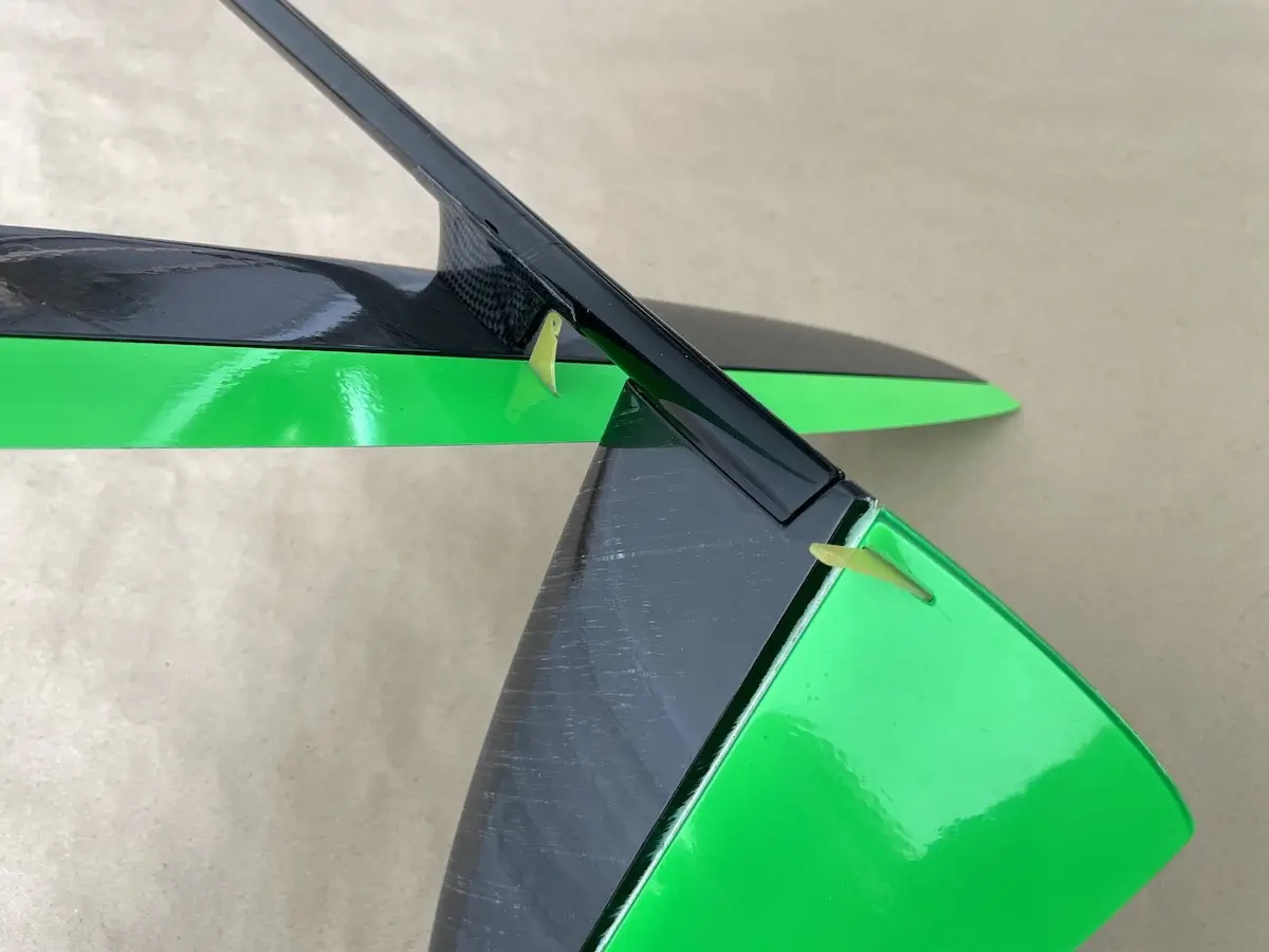
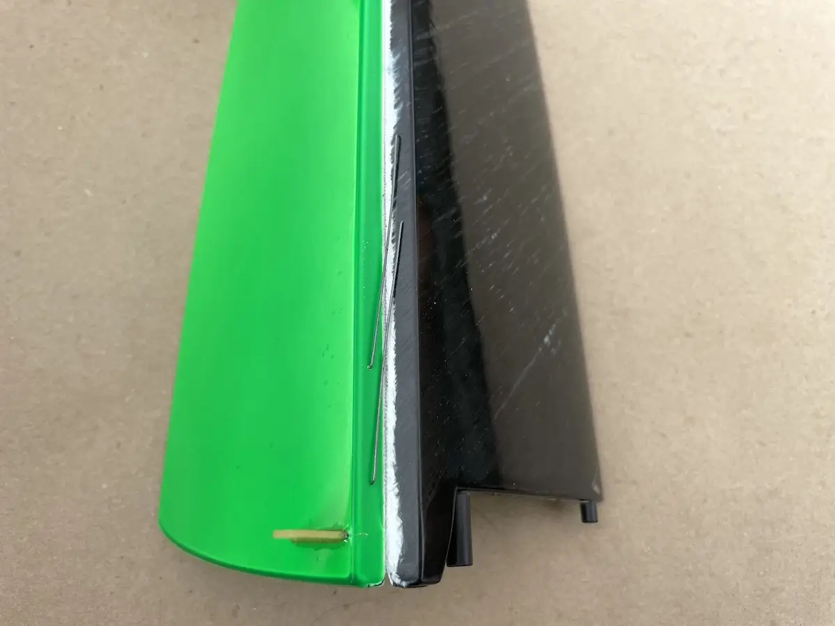
Since the wing has a composite construction, check the video below to identify a “flat” position of the control surfaces relative to the wing body.
Recommended throws and camber settings
For the initial setup, please use the following recommendations on the settings and adjust them depending on your preference.
Joy F5J Control Throws and Camber Settings
CG Position
At the ballast tube spot in the wing
Rudder
+/- 25mm
Elevator
+/- 15mm
Ailerons
+/- 14mm (Ail to Flap: +/- 6mm)
Brakes
Flaps: 25-30mm down, Ailerons: 15mm down or 7mm up
Cruise
Flat bottom of the wing (0mm)
Speed
1-3mm up
Thermal 1
3mm down
Thermal 2
8mm down
Happy flying!
3 thoughts on “Joy F5J Build Instruction”
Bruce Pearson
I saw 2 of the Joys at the field a couple days ago. Instantly recognized not what it was but at least what it could do! These were owned by Doug (winchdoc) and Vic T. I would very much like to have one but I see that they are out of stock, are there any available? Will there be any soon?
I think I would like Tiger 1, with your power train.
I will be standing by hoping and awaiting any news!
Bruce
We a working towards getting them back in stock but it will take some more time.
-Gene
My new Joy arrived a couple days ago, absolutely beautiful!