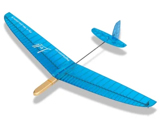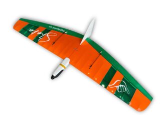
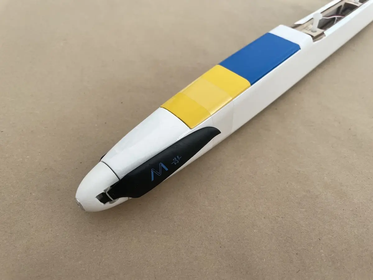
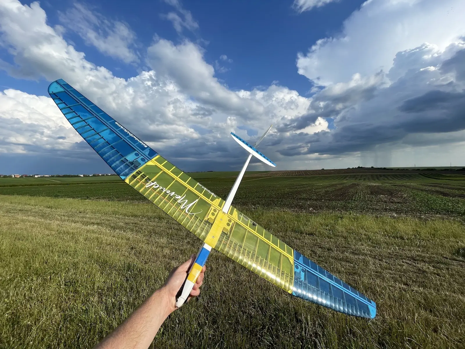
Maverick is a 1.5-meter full-house balsa RC electric glider designed for thermal hunting and F5K competitions.
It features mainly wooden construction, reinforced with composite tubes and rods.
The entire design of the kit uses the idea of a simple build process that will make more people try F5K and thermal soaring. However, you will need to have some building experience already to finish this kit successfully.
Of course, make sure to prepare your RC tool kit before starting with the build.
For some inspiration, build tips flight reports, and more, check Maverick RCGroups Thread, and feel free to share your builds there as well.
Sharing is caring!
Below, you will find an instruction on how to build this model.
Let’s get started!
Video Instructions by BavarianRC
Video Instructions by Nick Chitty
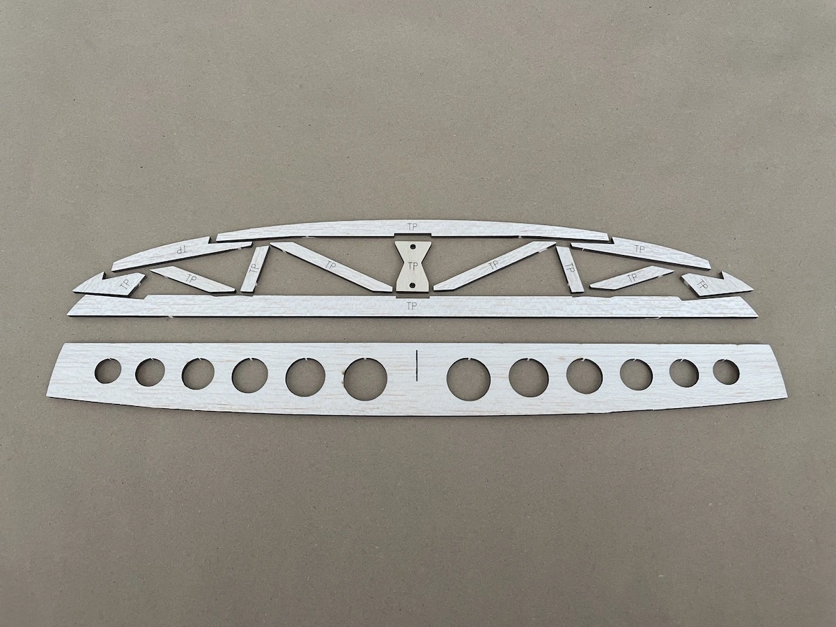
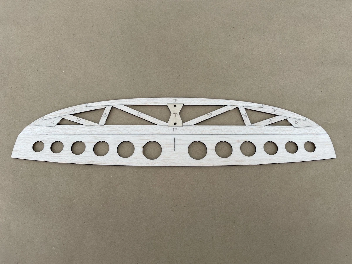
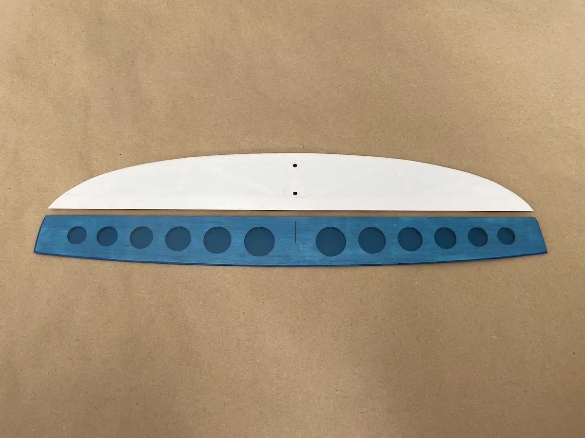
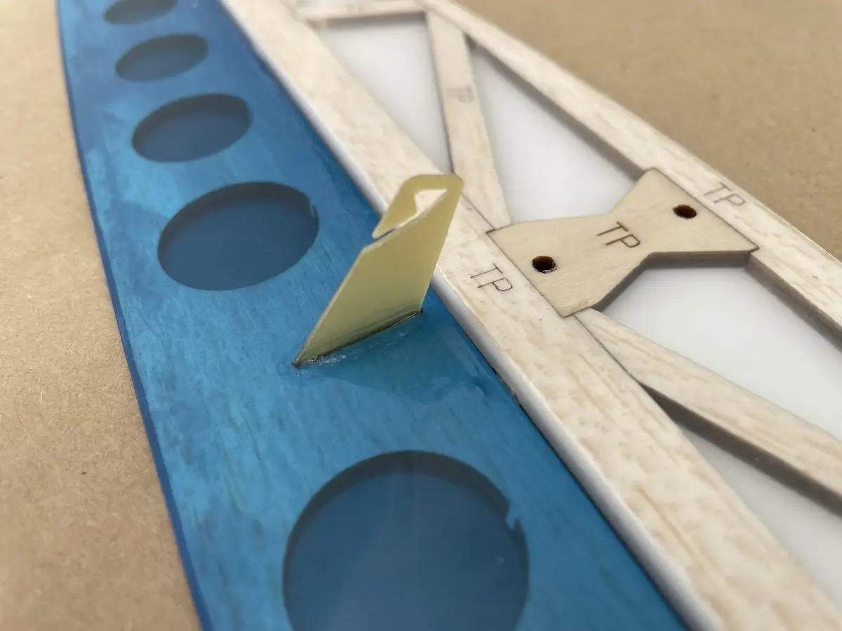
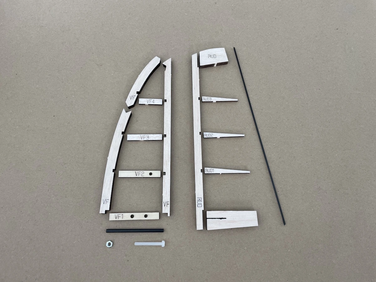
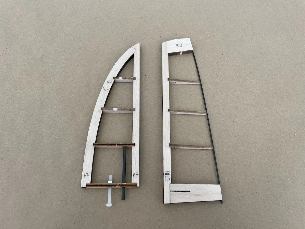
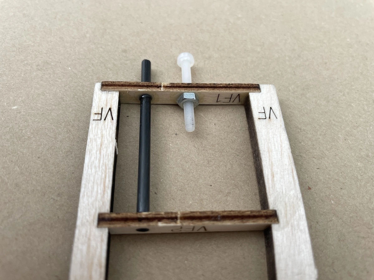
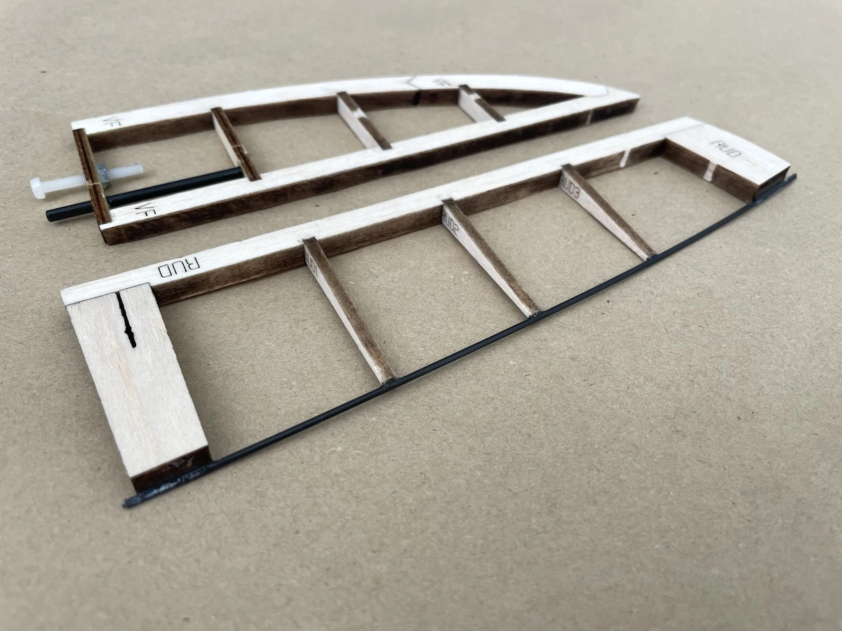
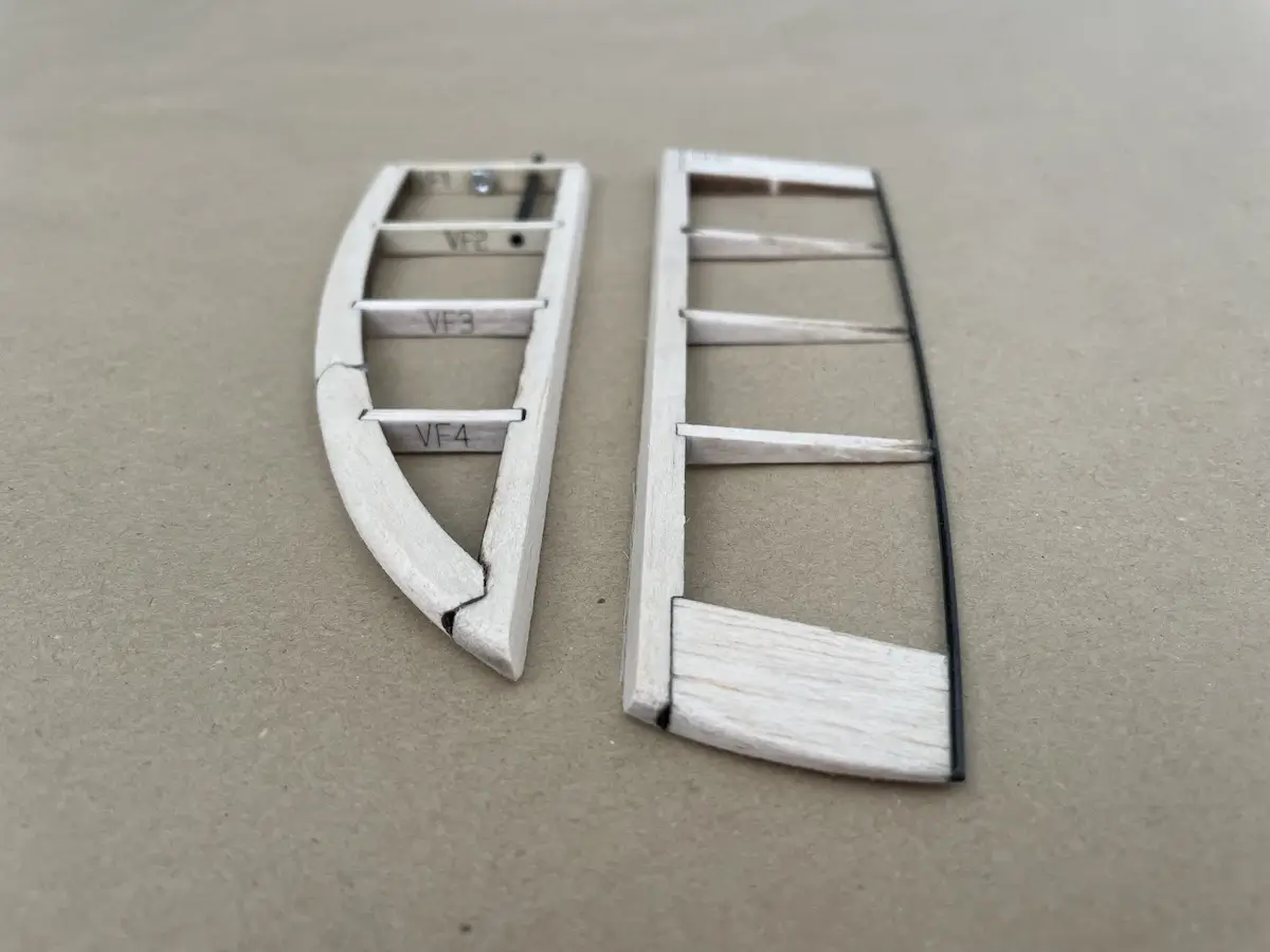
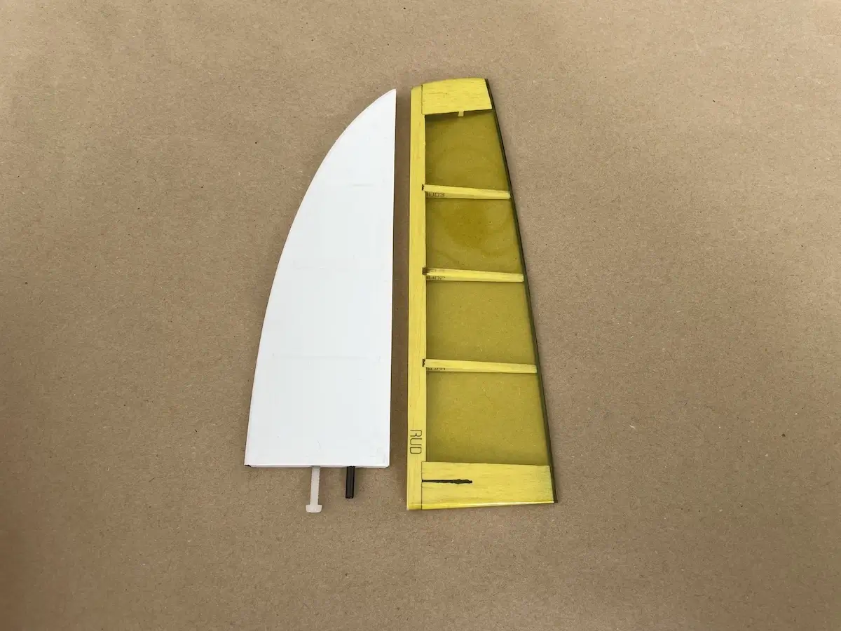
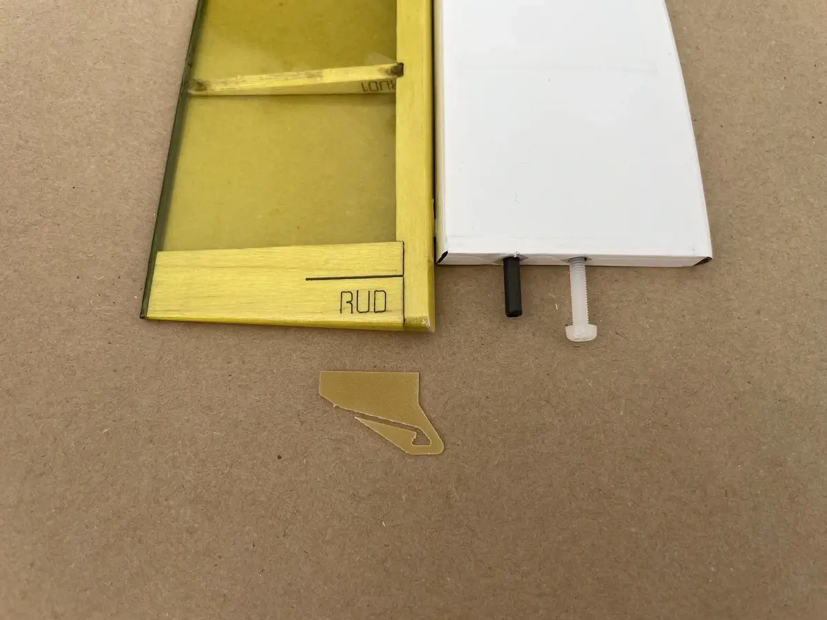
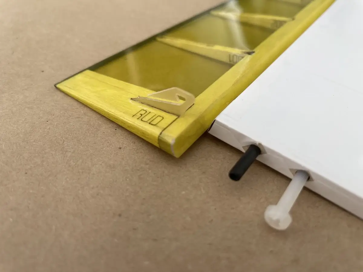
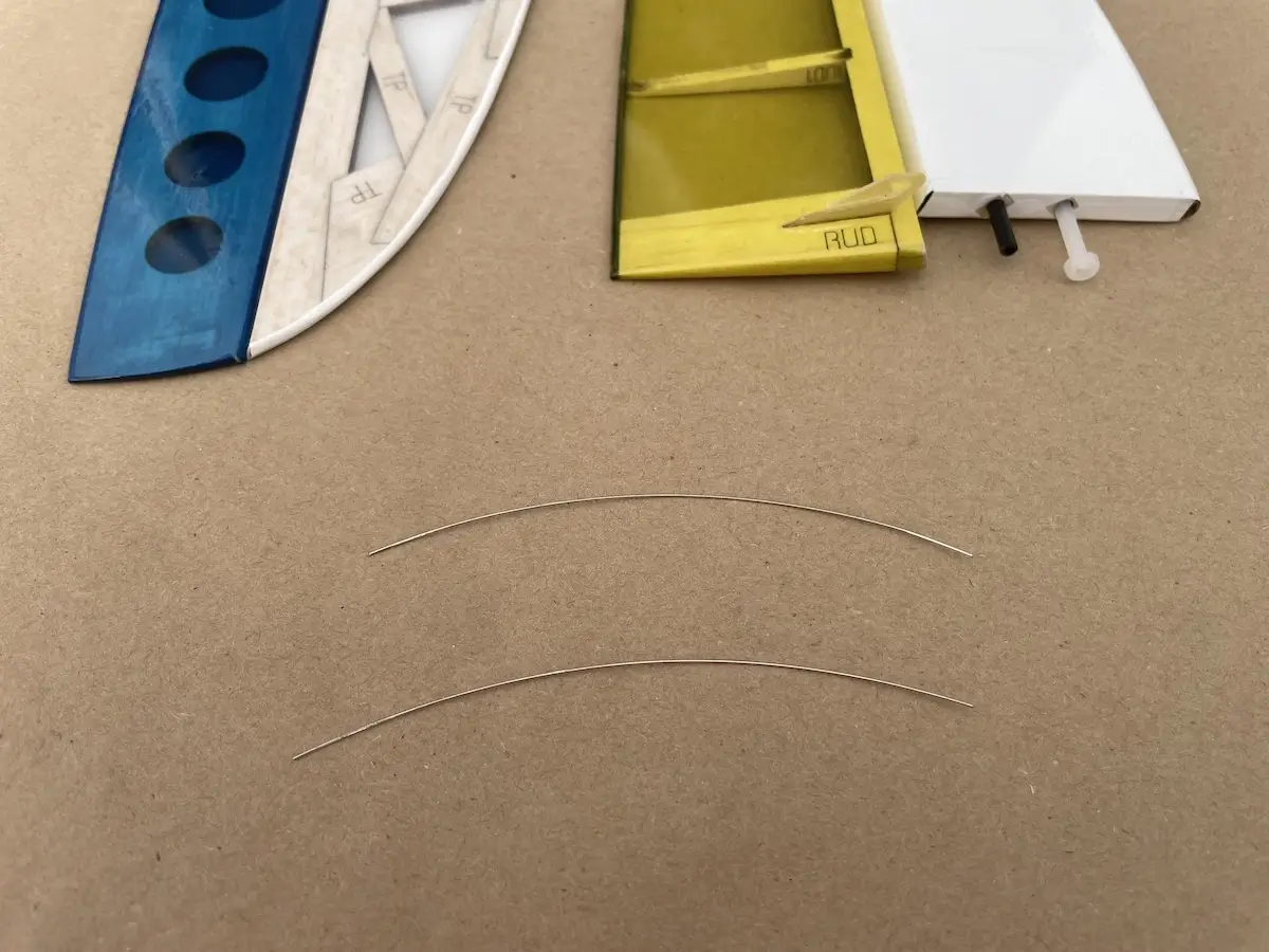
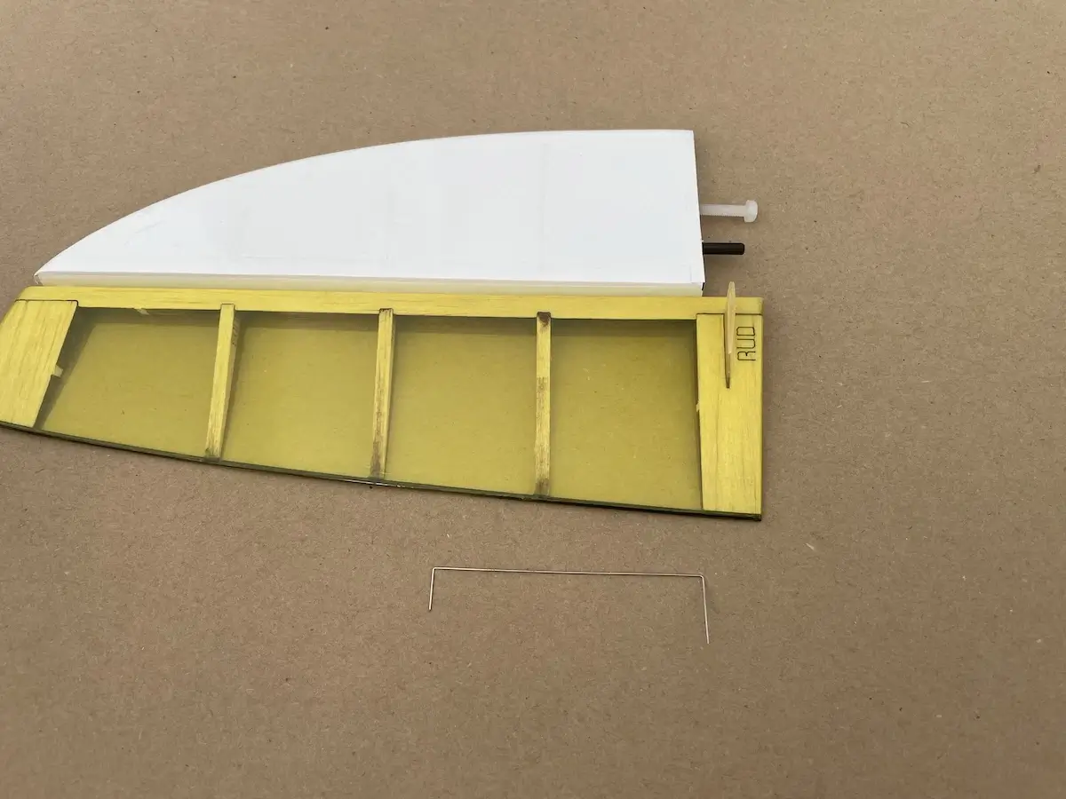
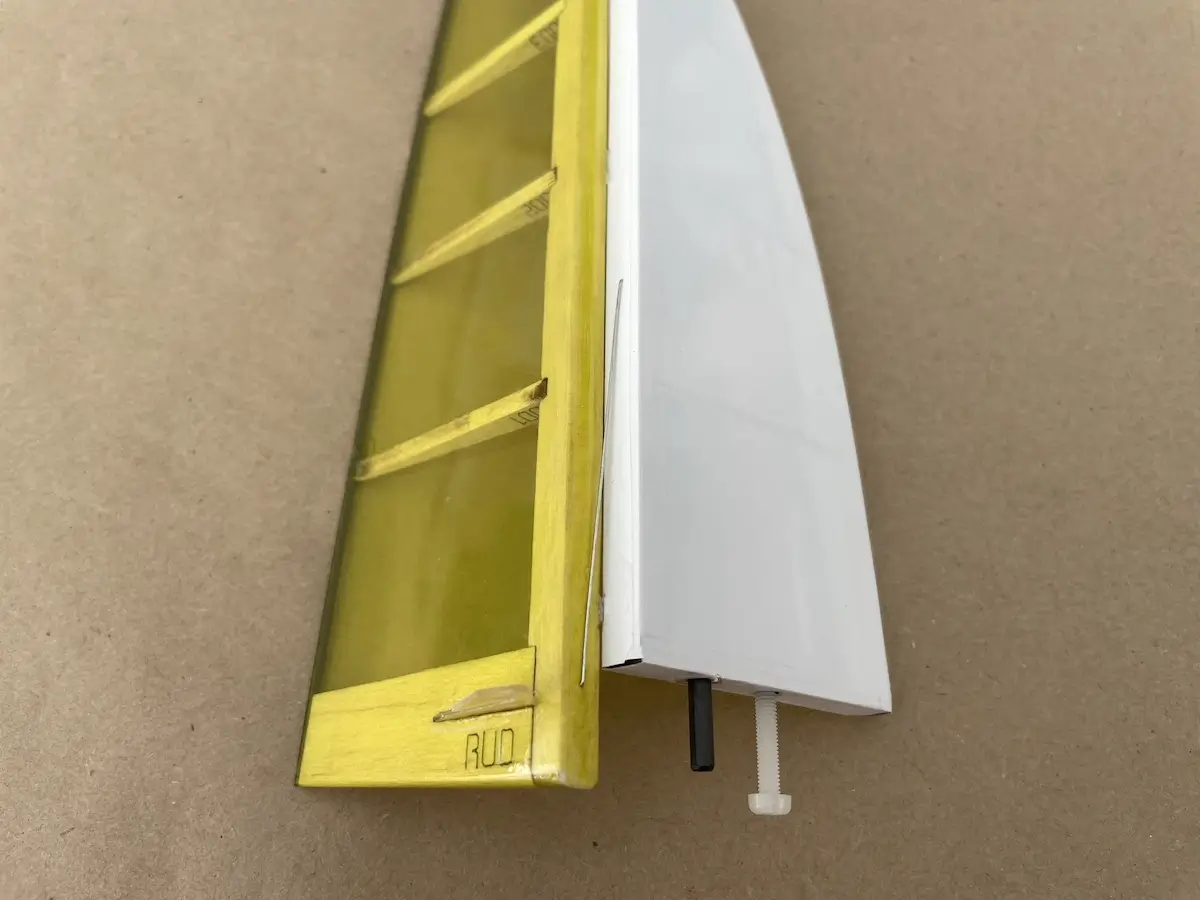
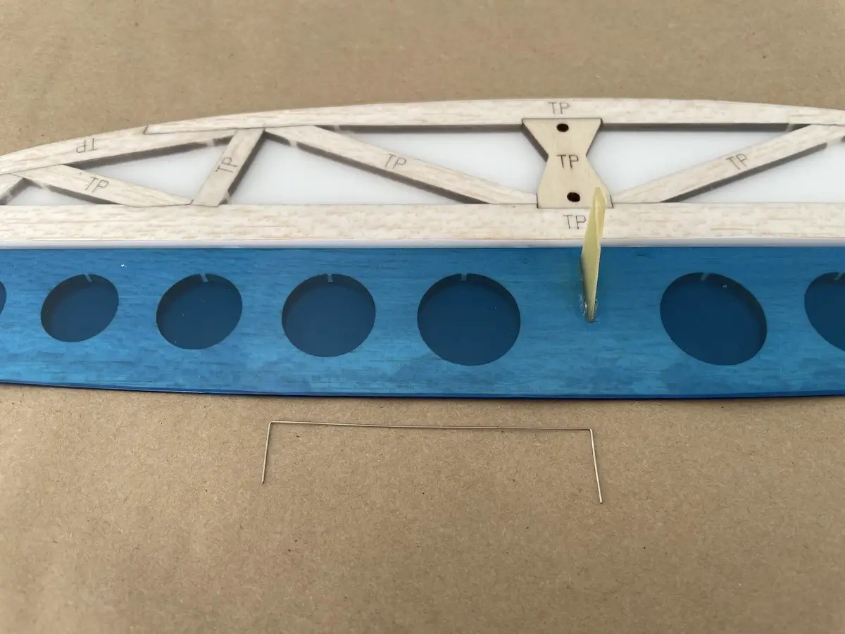
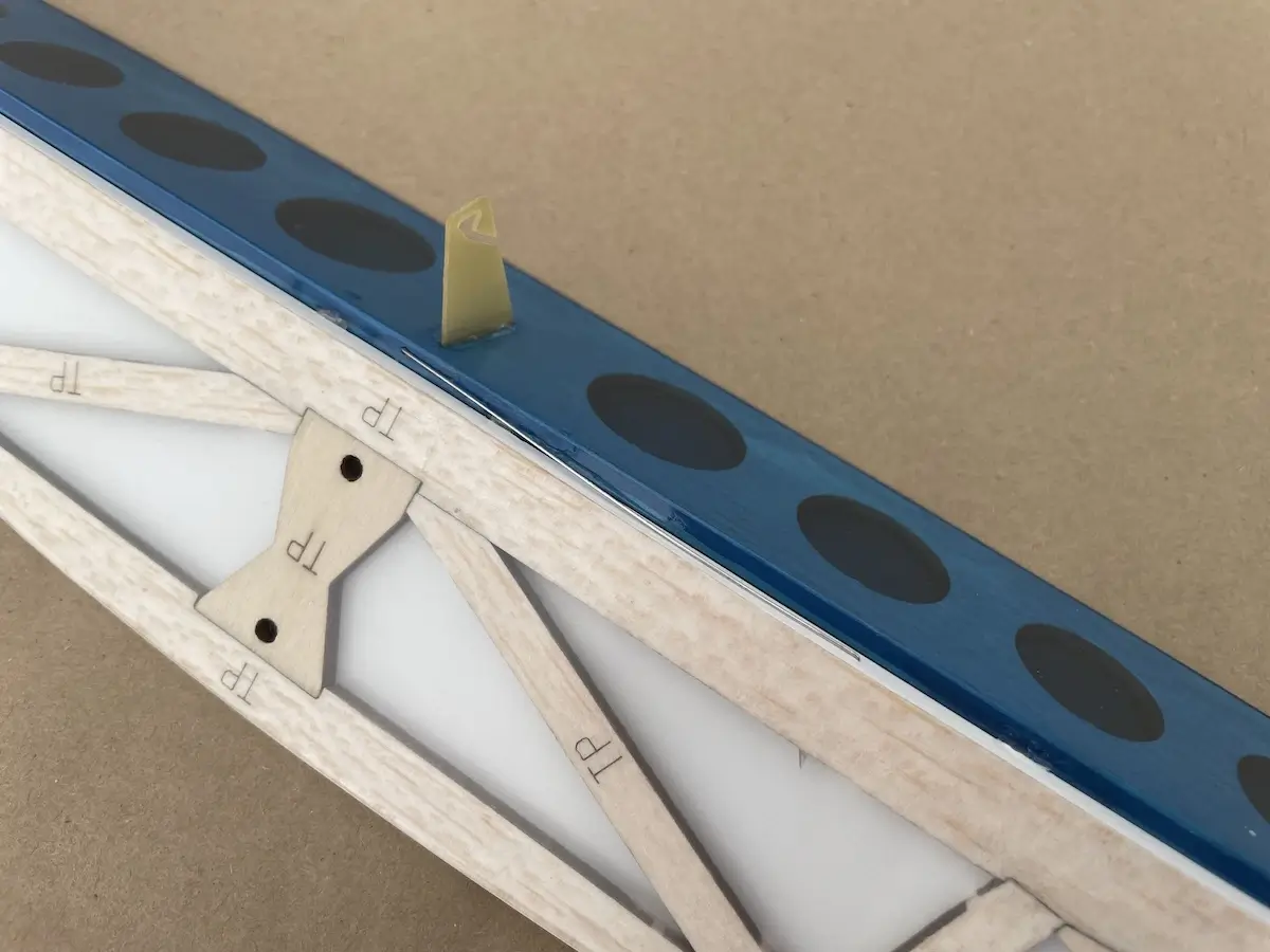
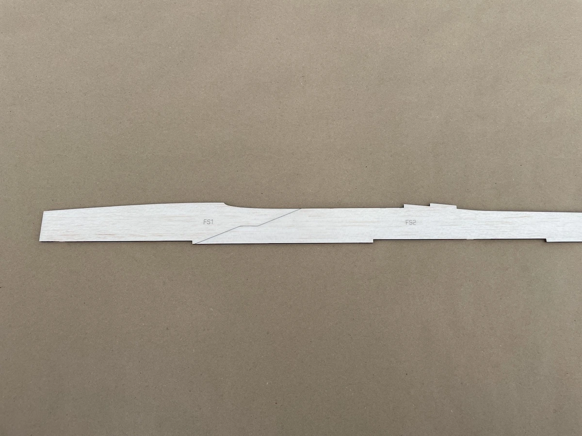
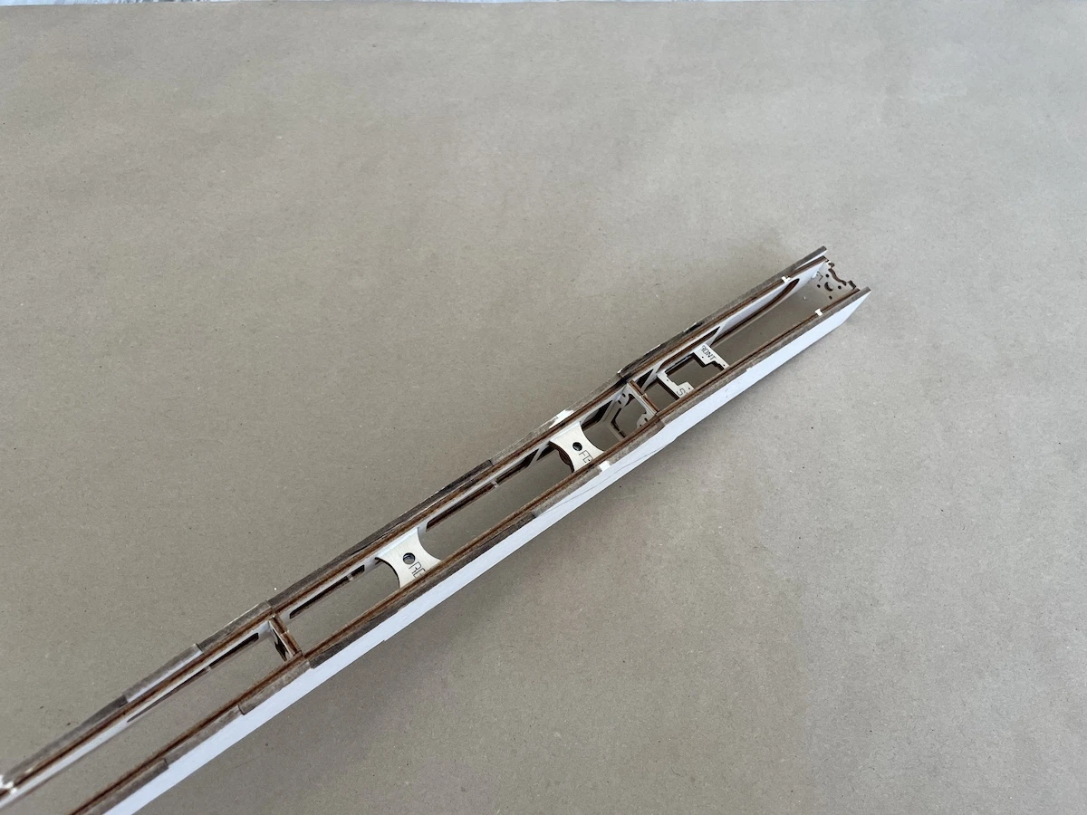
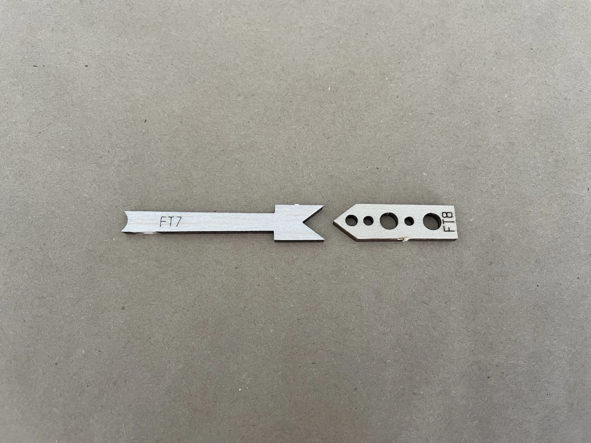
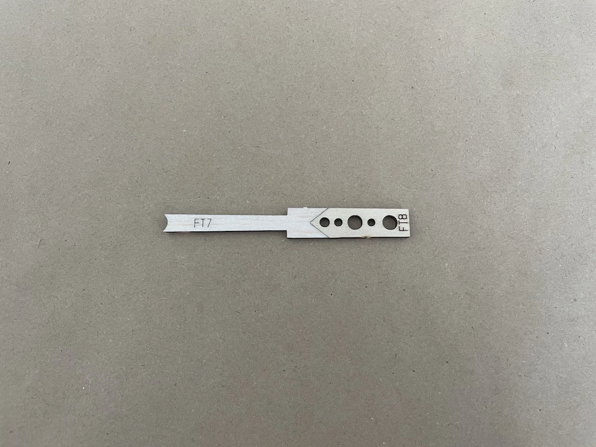
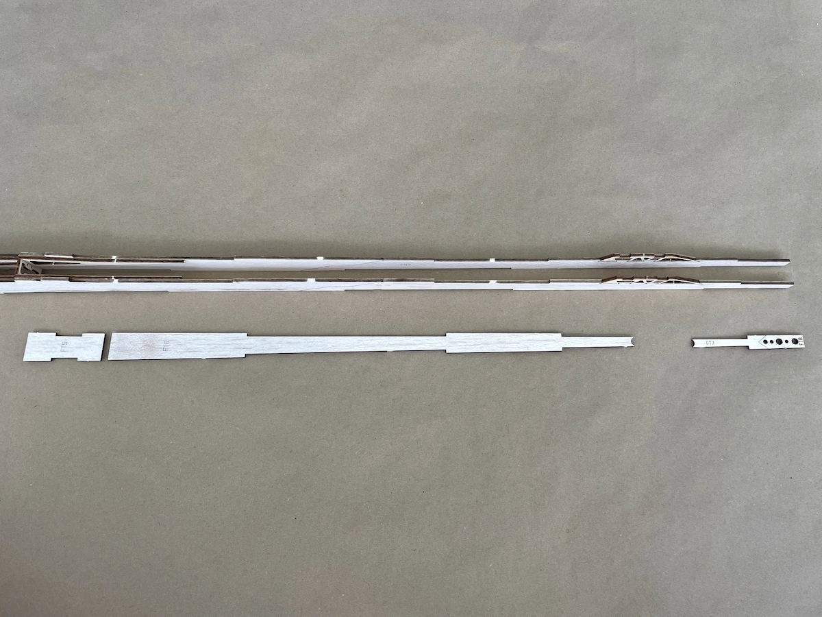
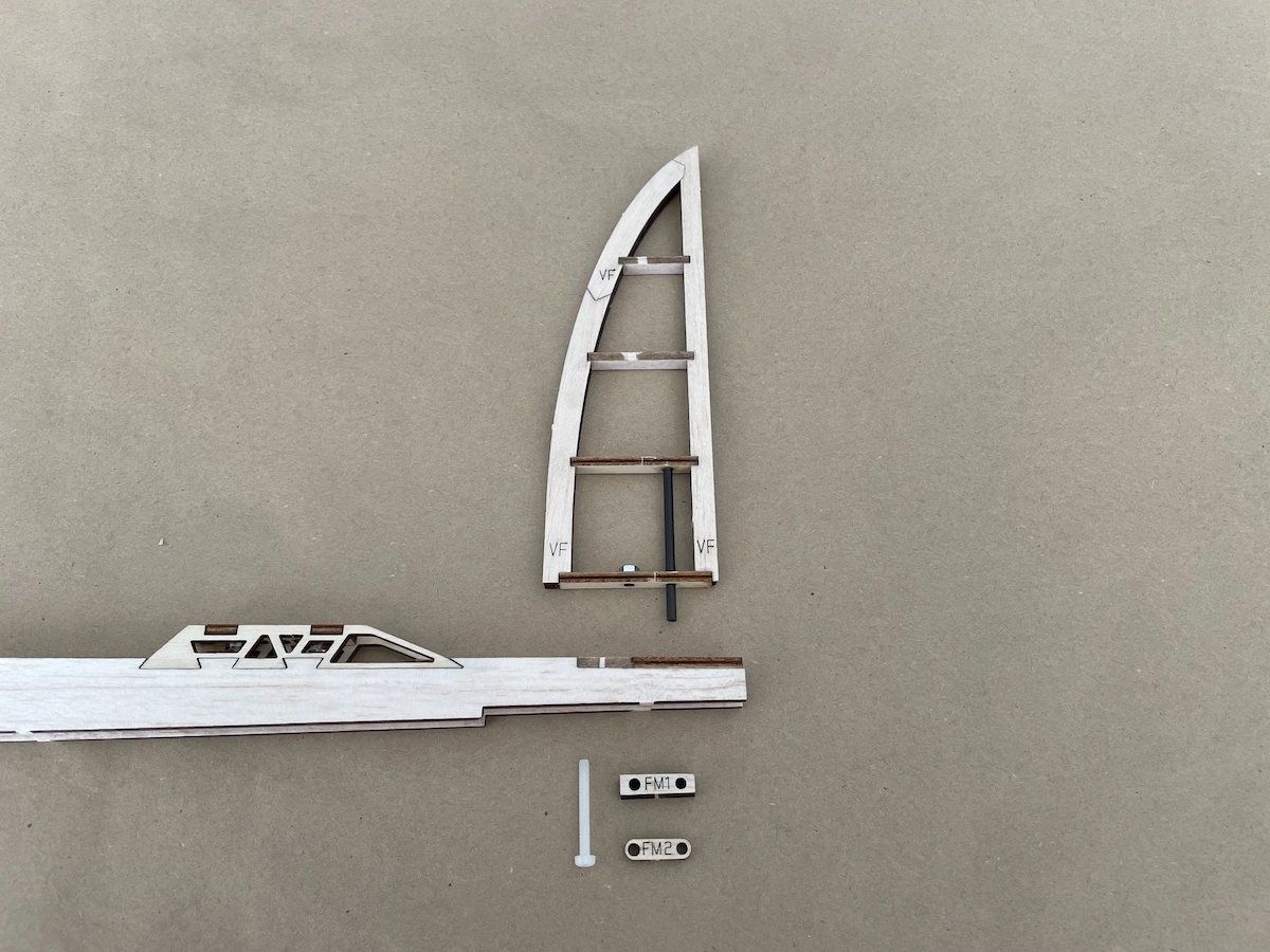
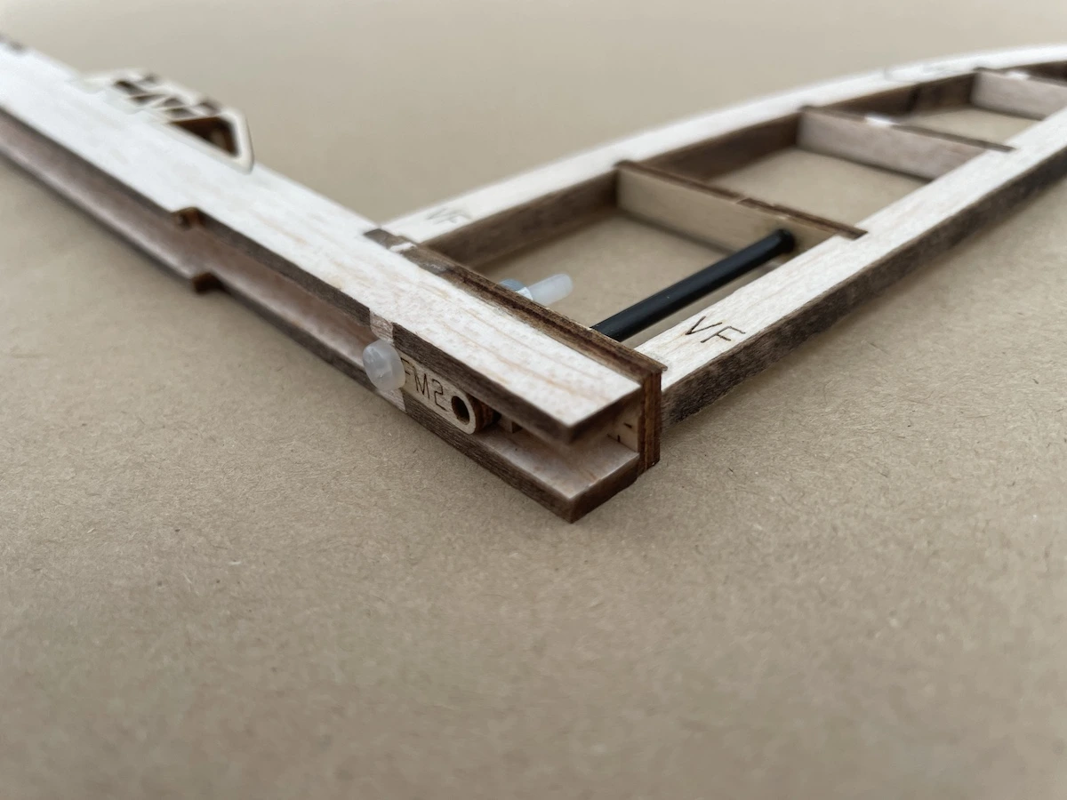
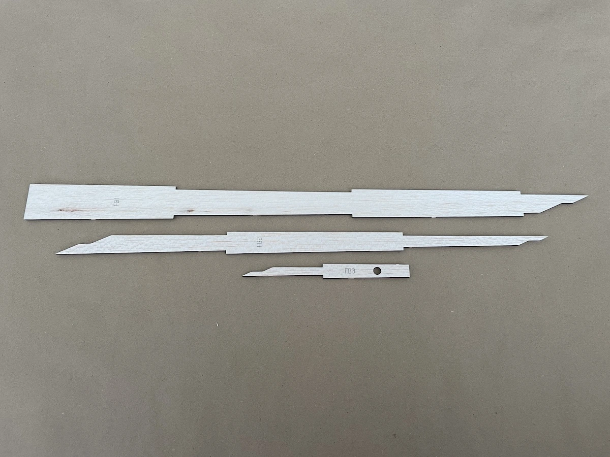
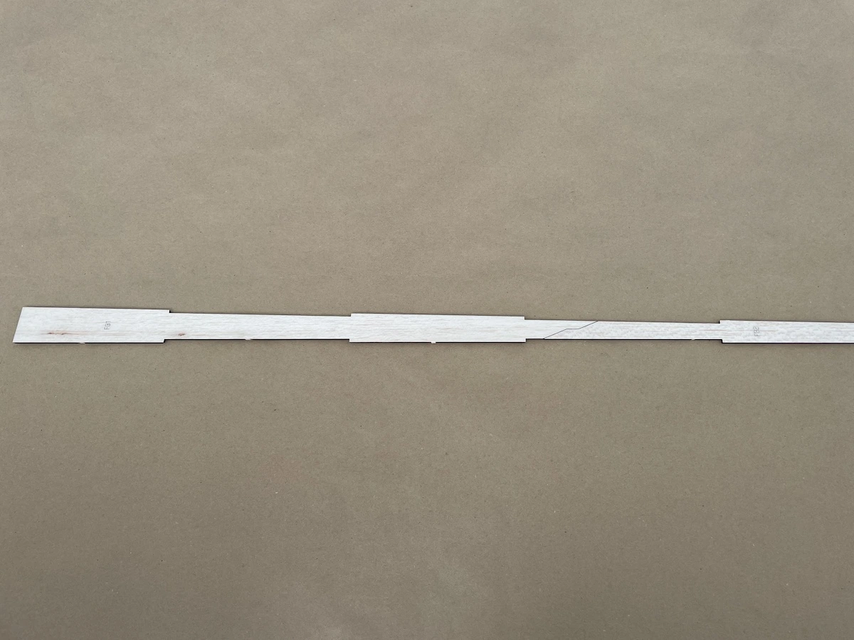
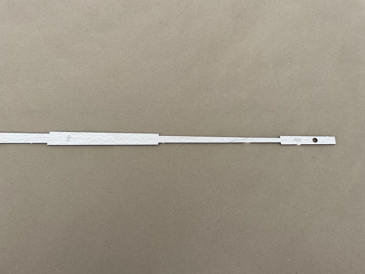
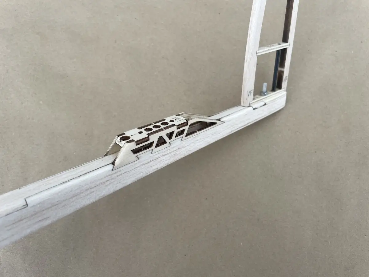
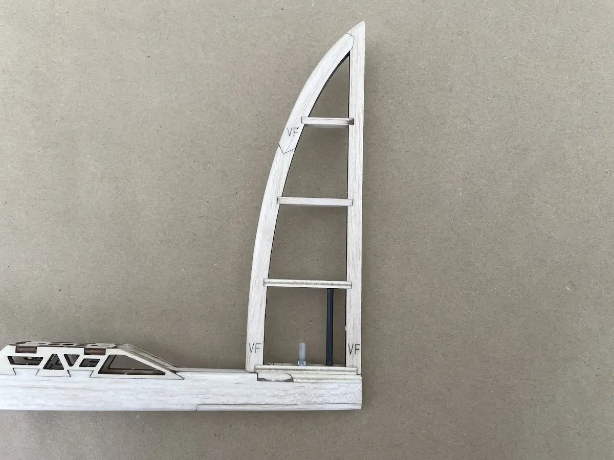
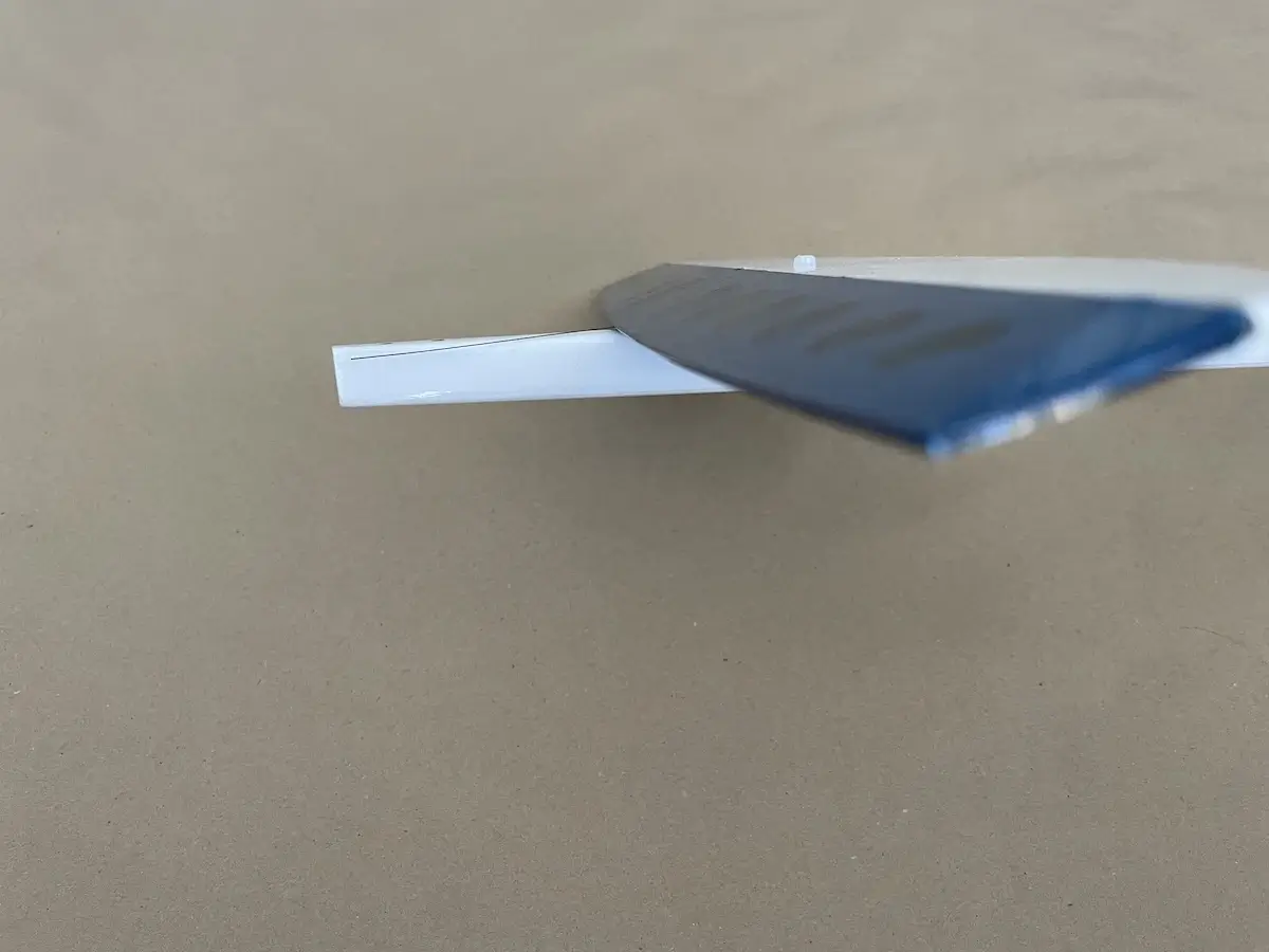
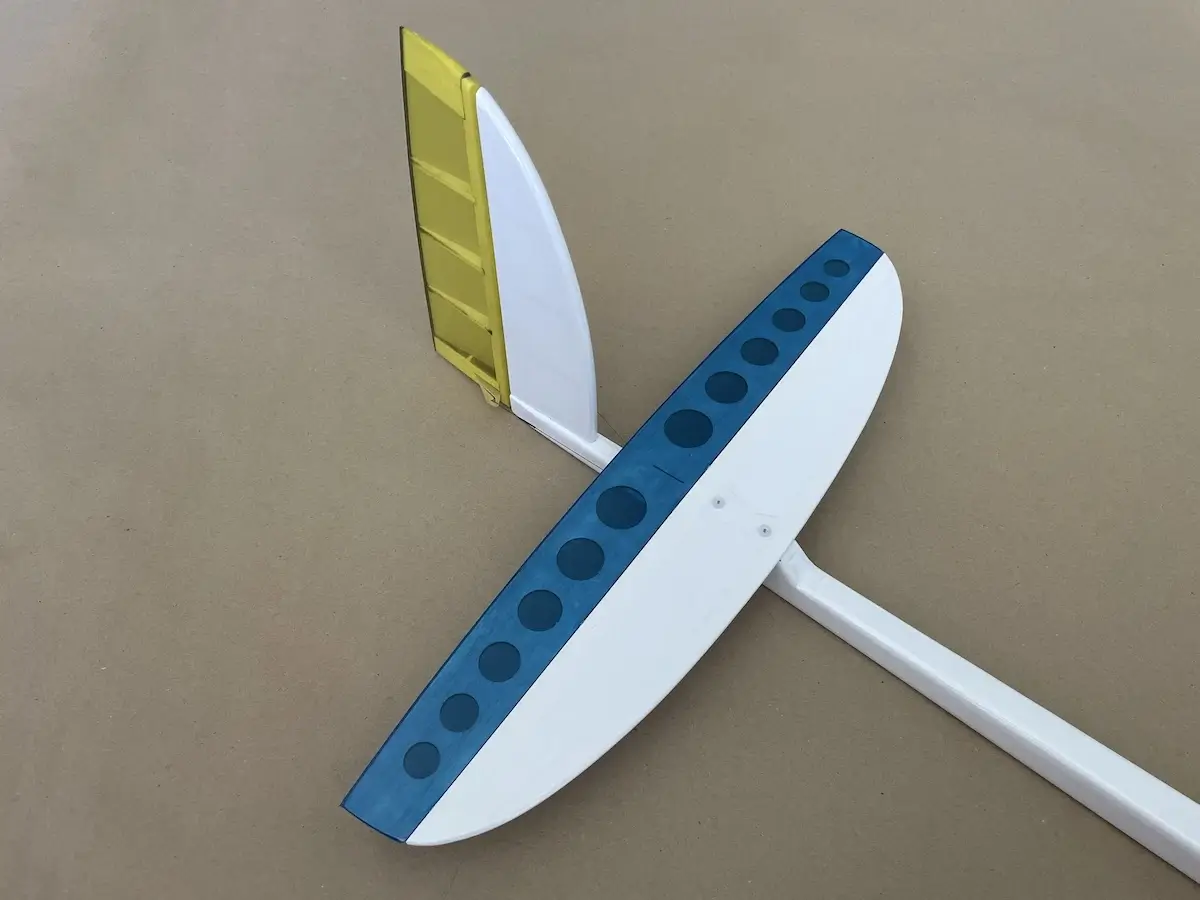
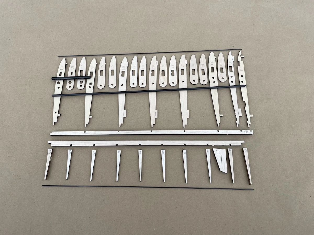
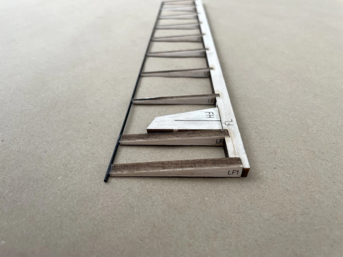
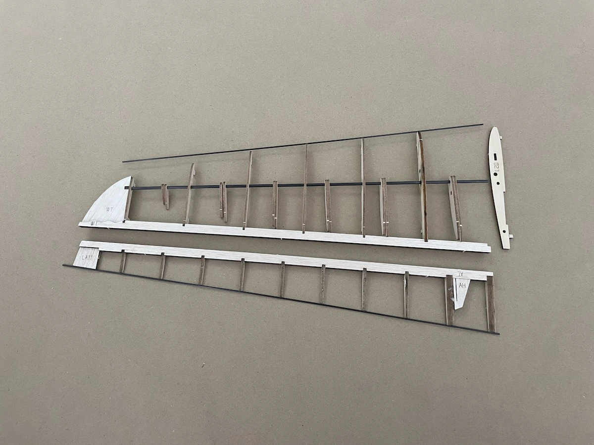
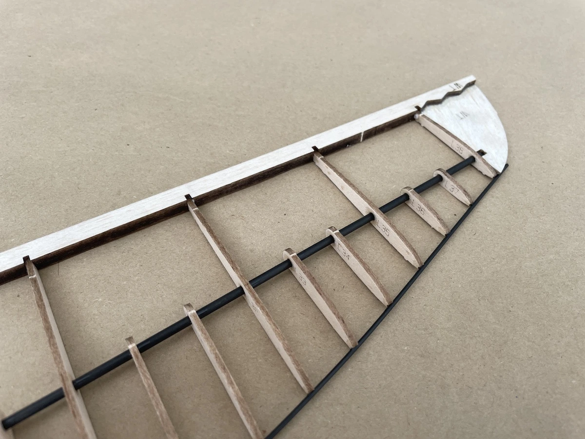
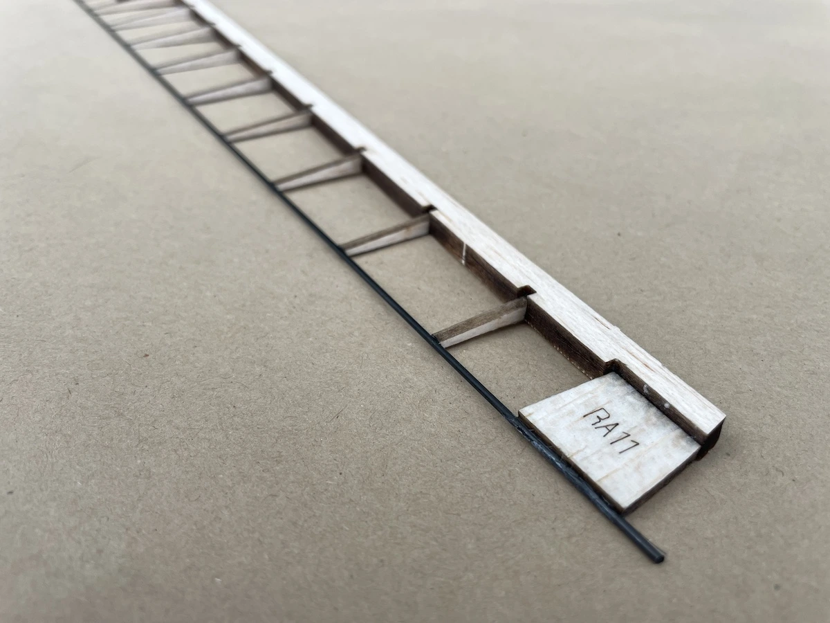
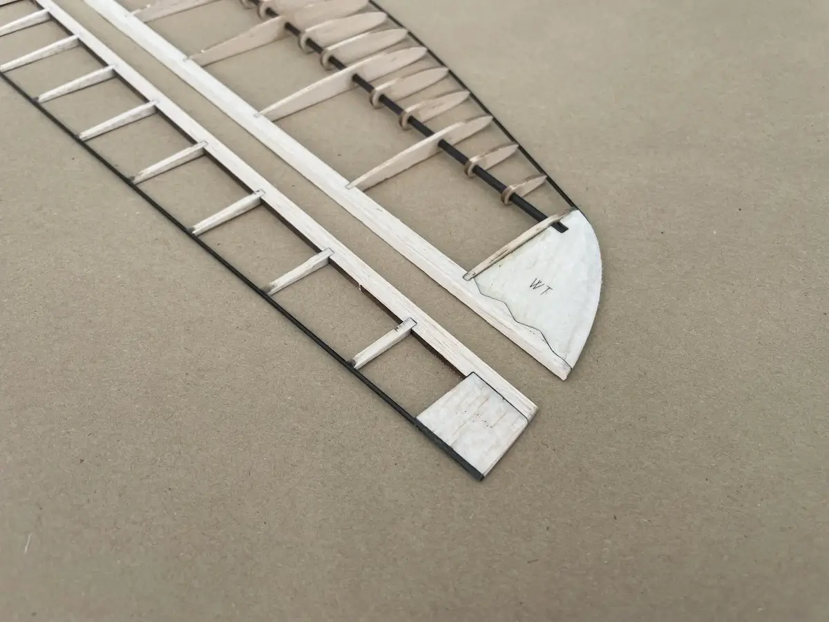
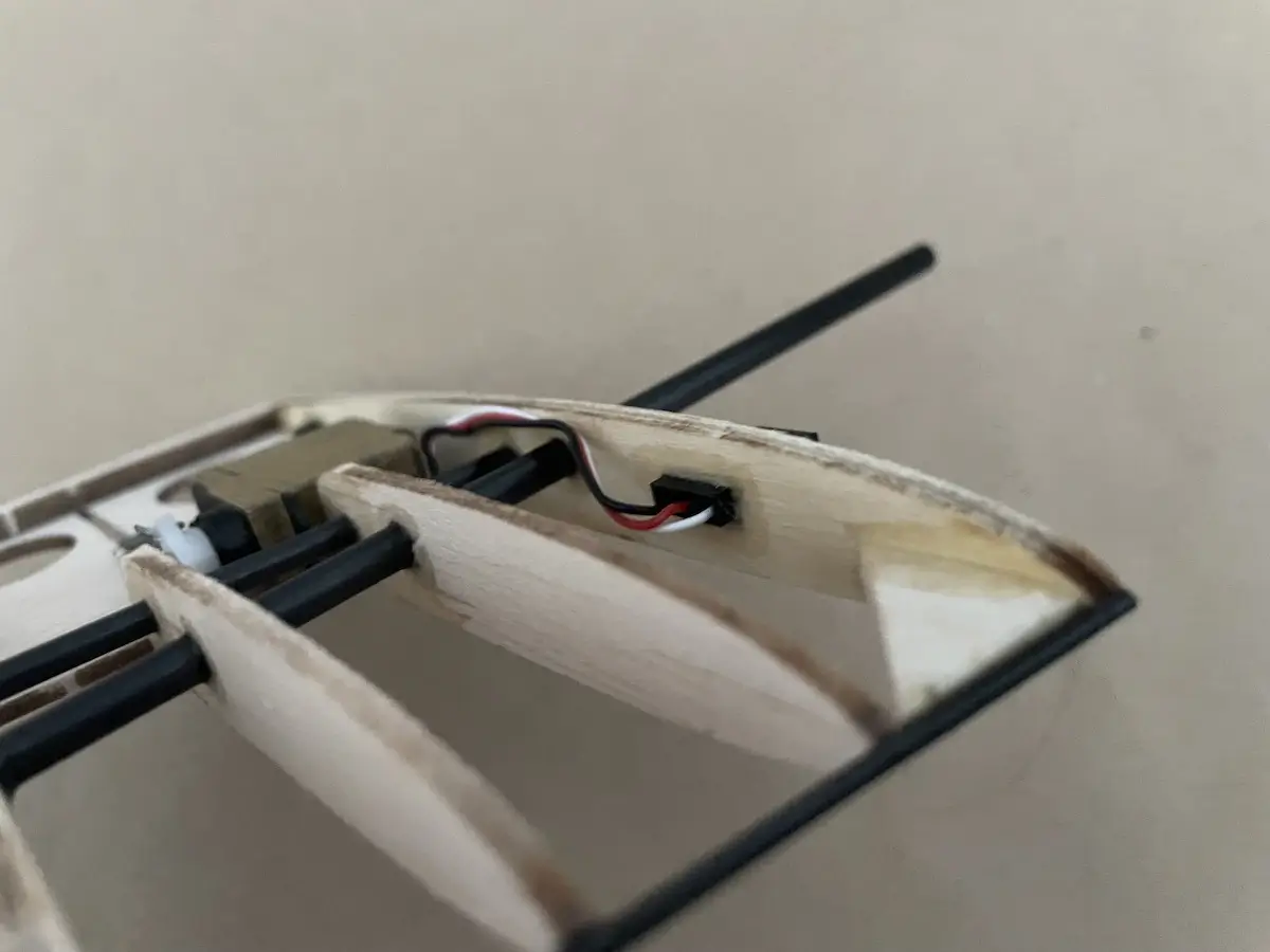
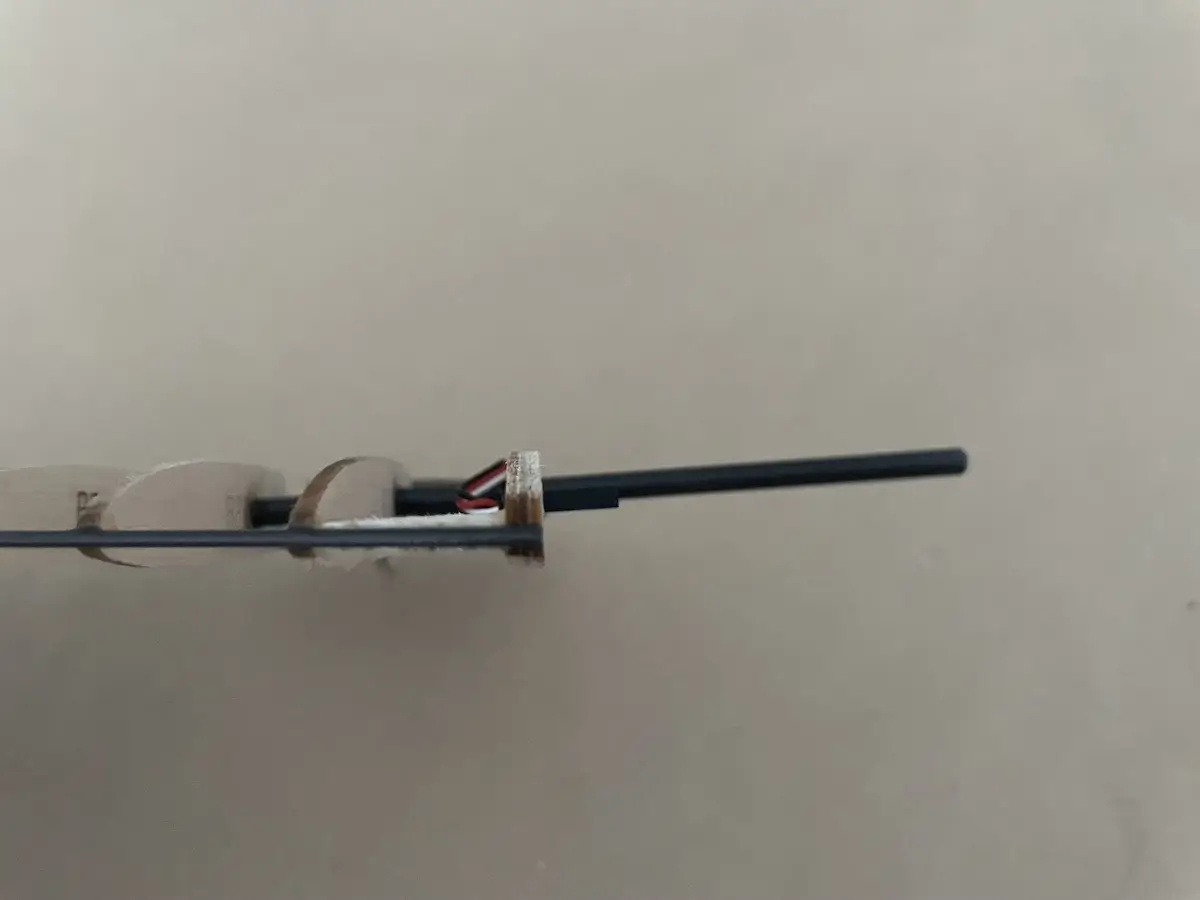
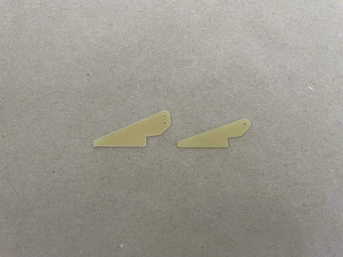
Part 1. Vertical Fin & Tailplane
Before you start, prepare a flat surface and use a plan provided with the kit as a reference for building a fin and tailplane.
Pro Tip:
Cover the plan with some clear film or clear sticky tape to avoid the kit parts sticking to the paper during assembly.
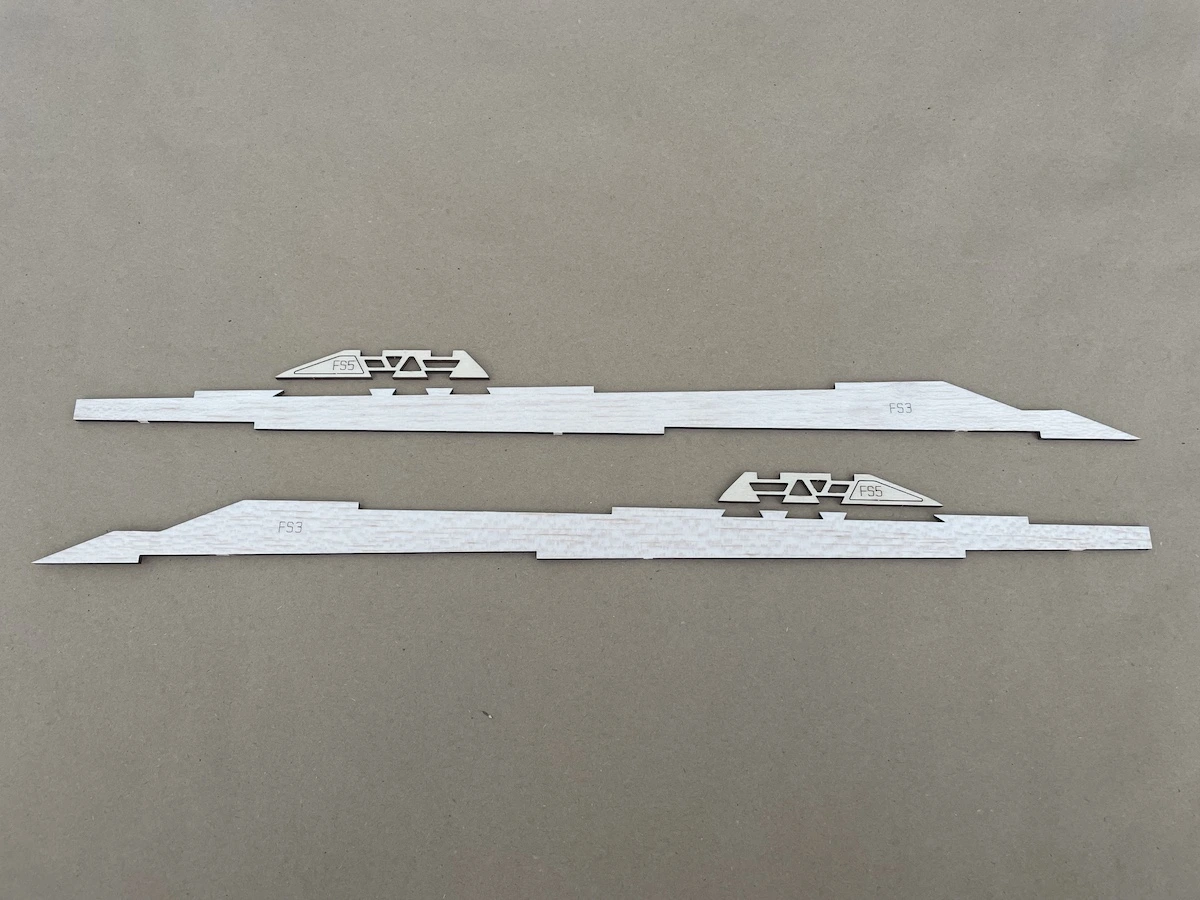
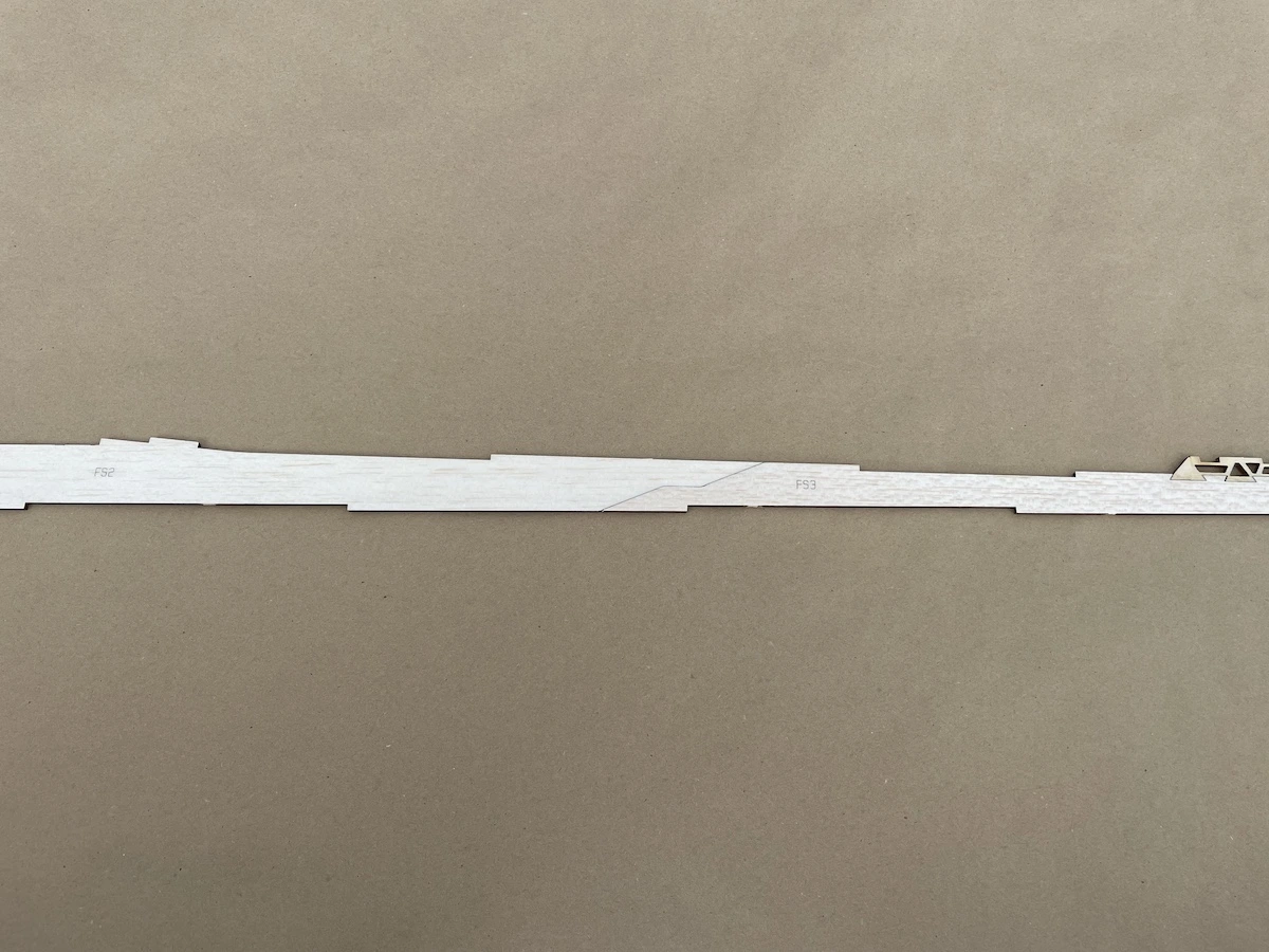
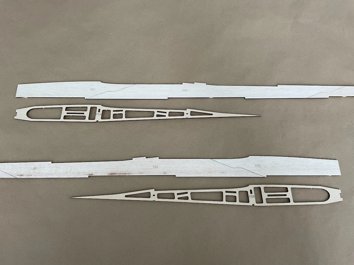
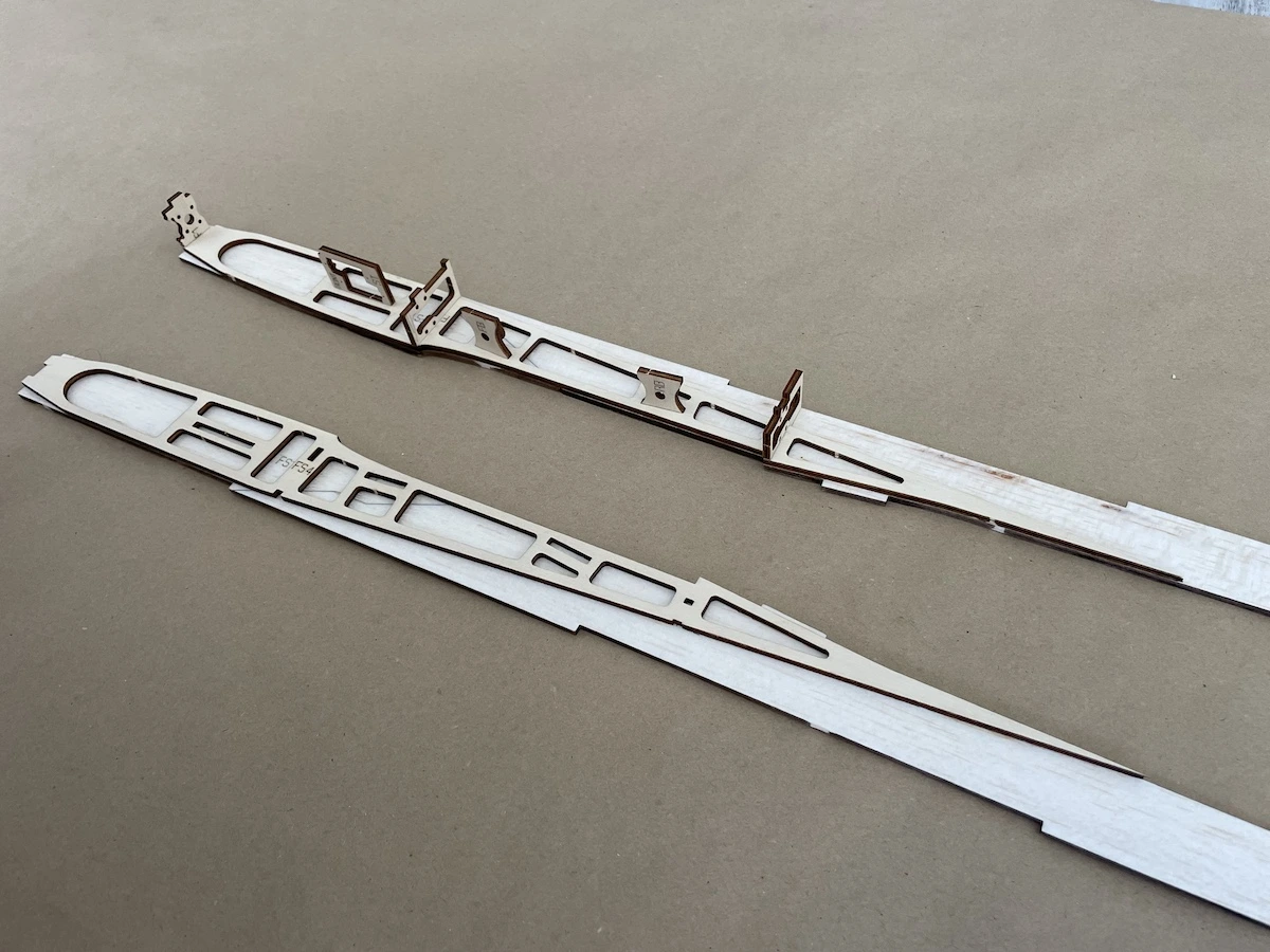
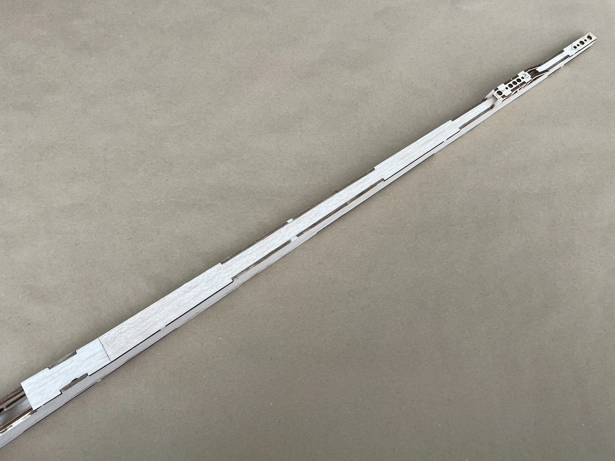
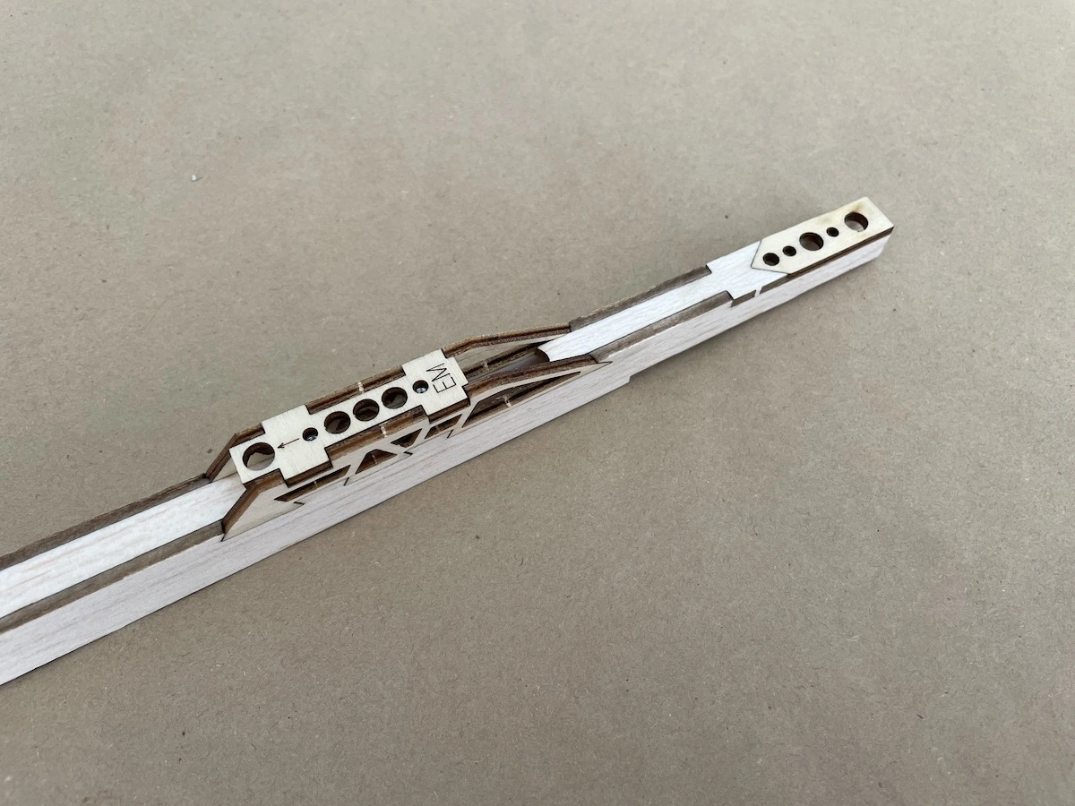
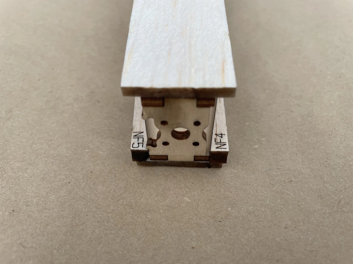
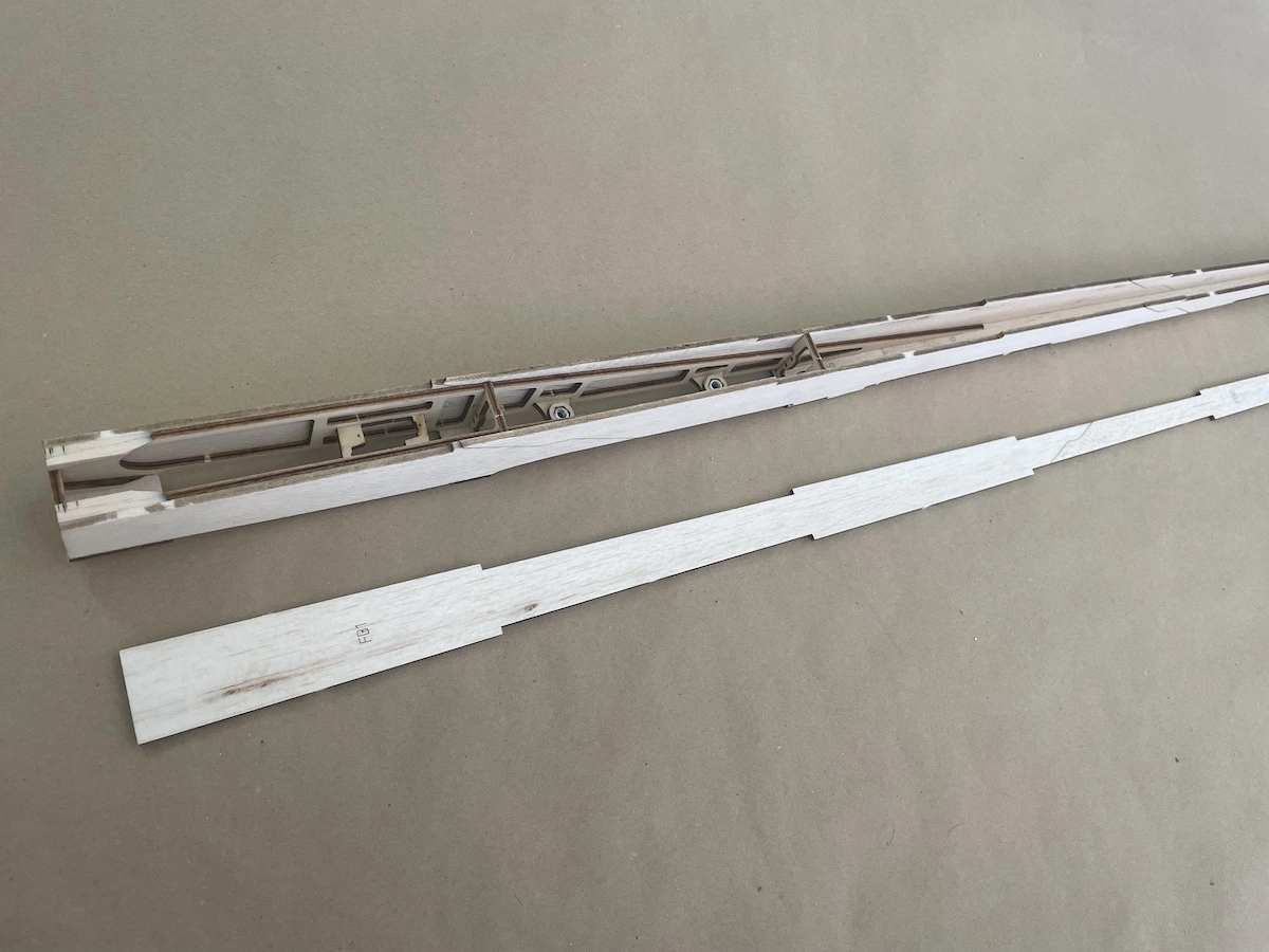
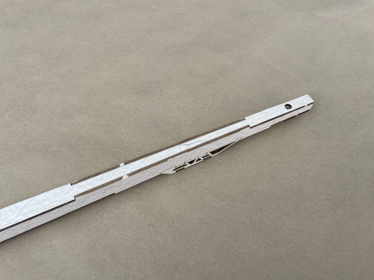
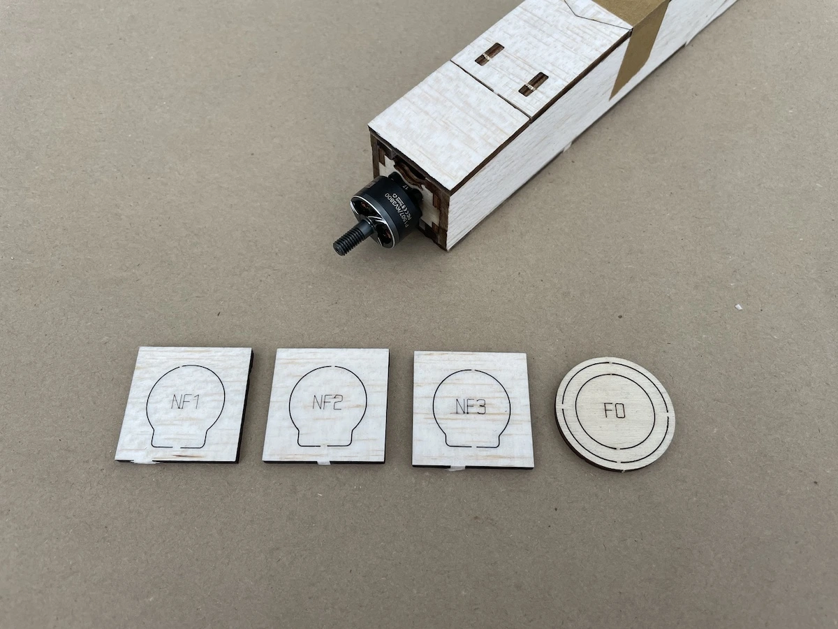
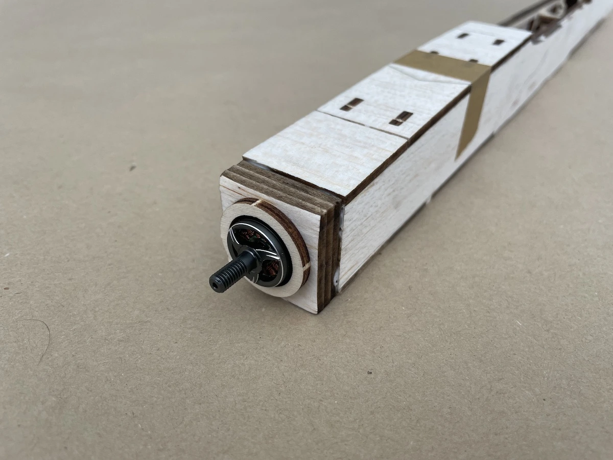
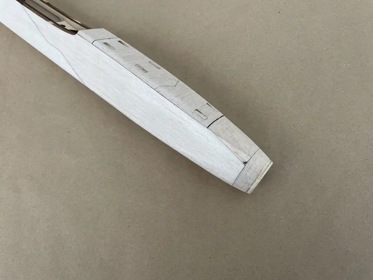
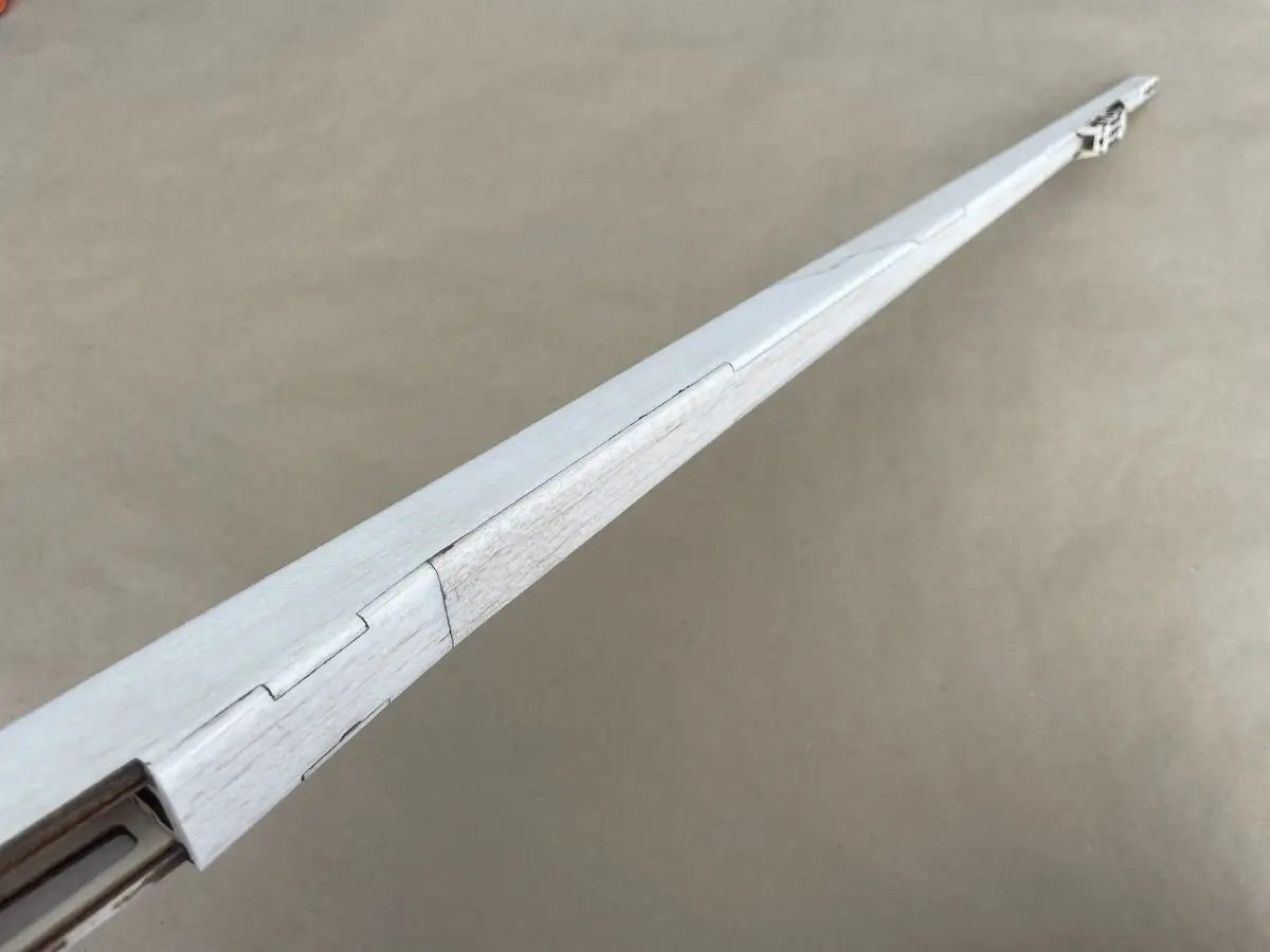
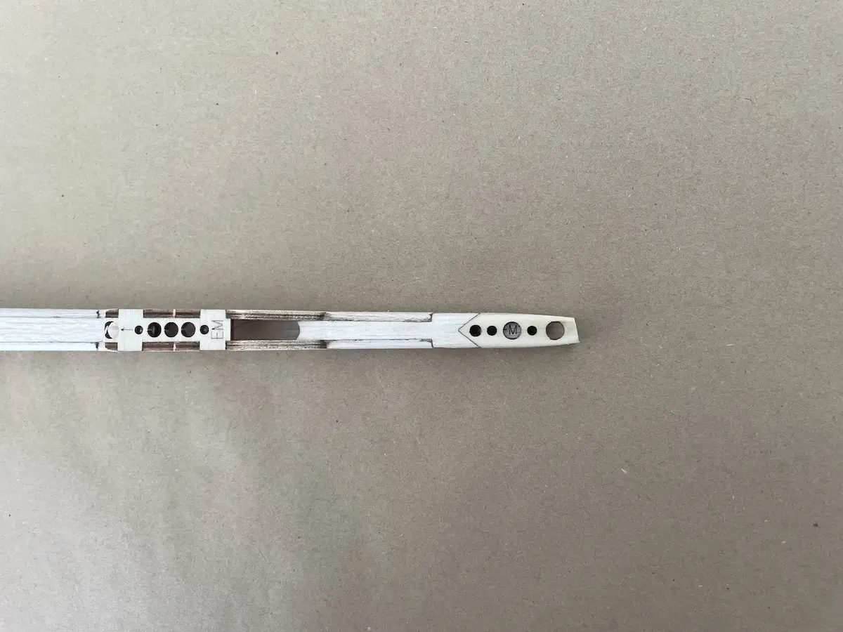
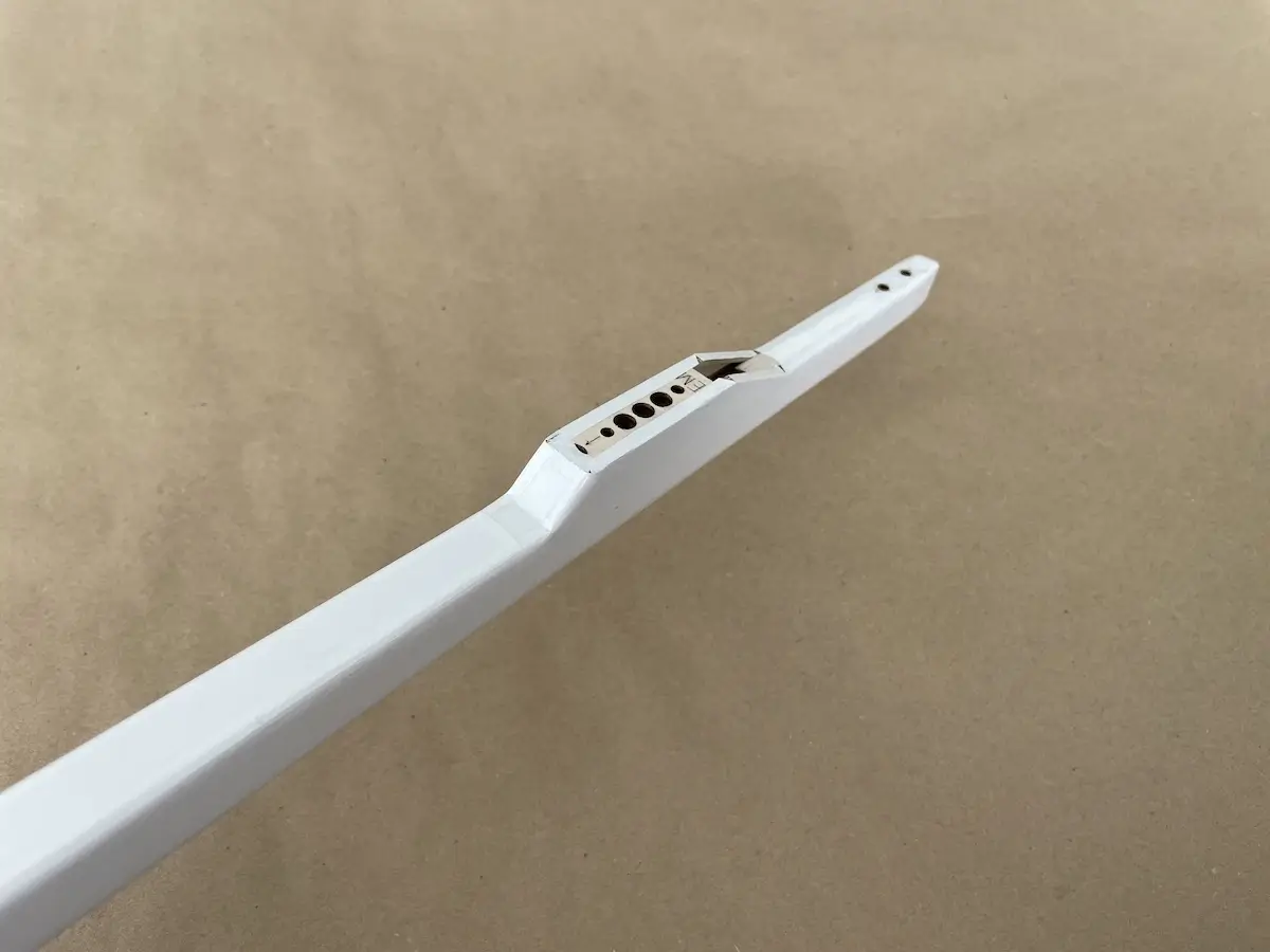
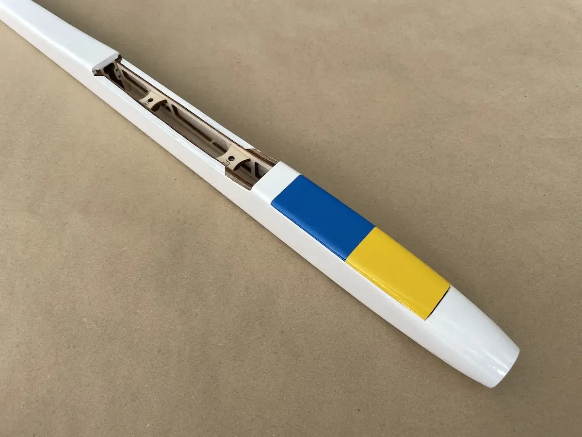
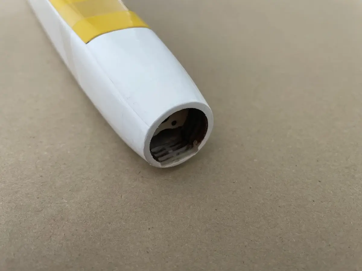
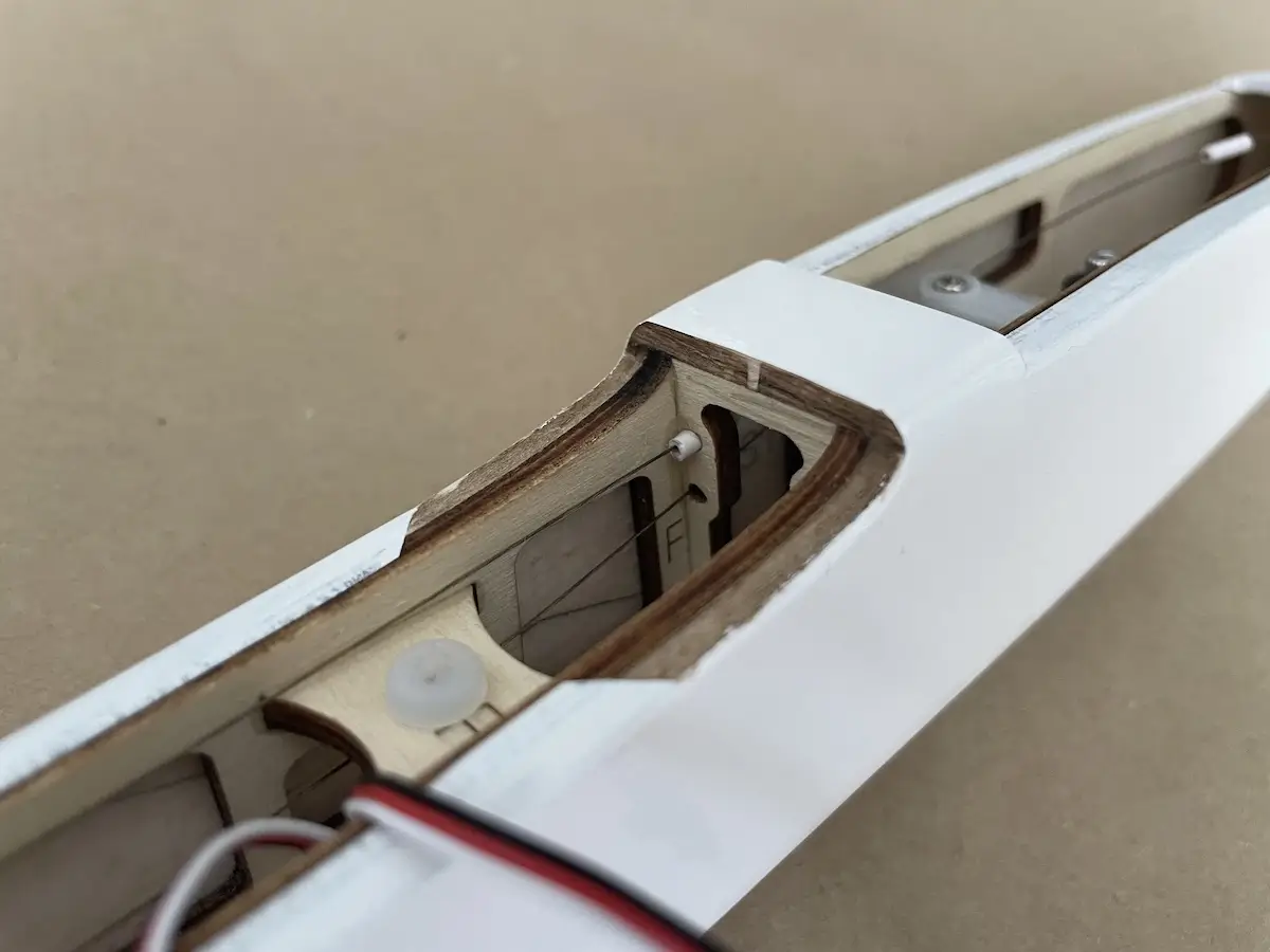
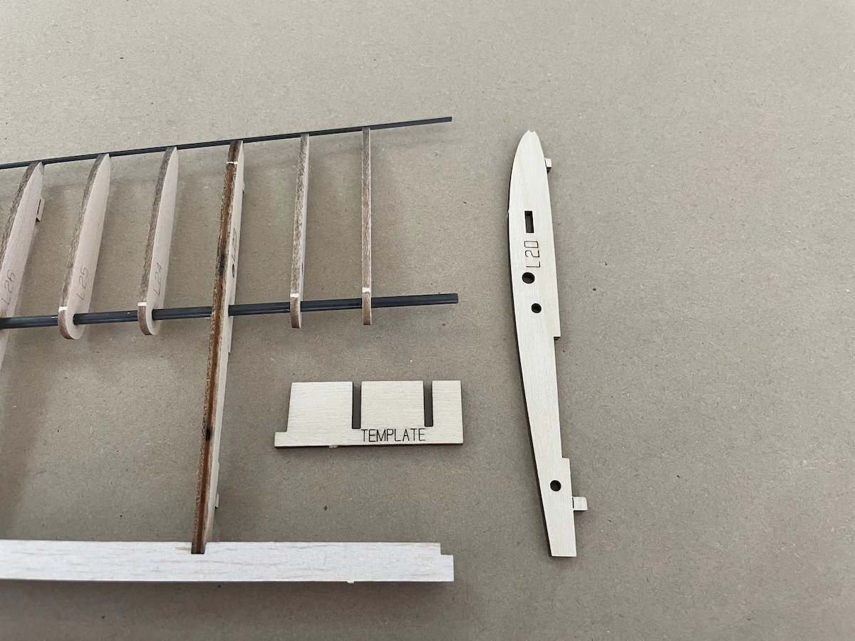
Part 2. Fuselage
Pro Tips:
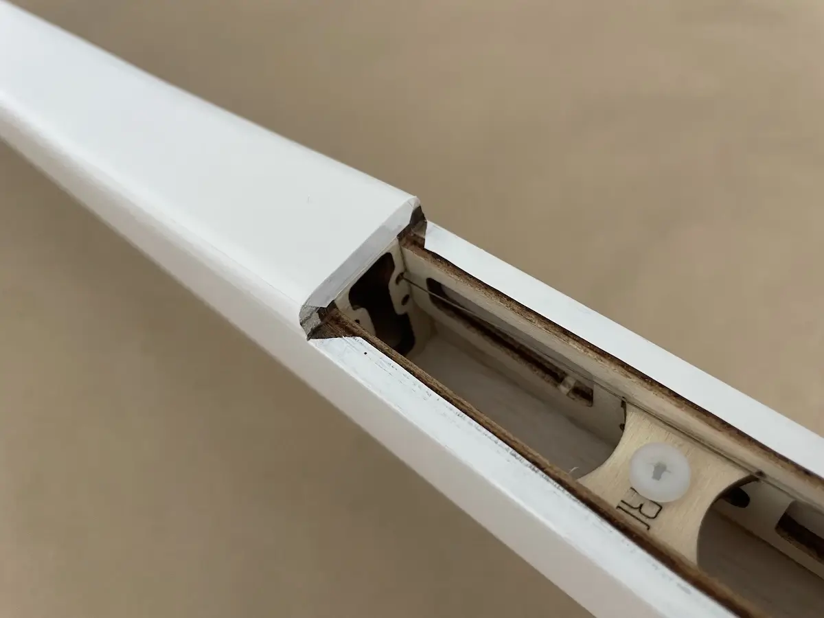
- Use a flat surface to build your fuse.
- The bottom and sidewalls of the fuse are designed to be completely flat to make it easier to assemble.
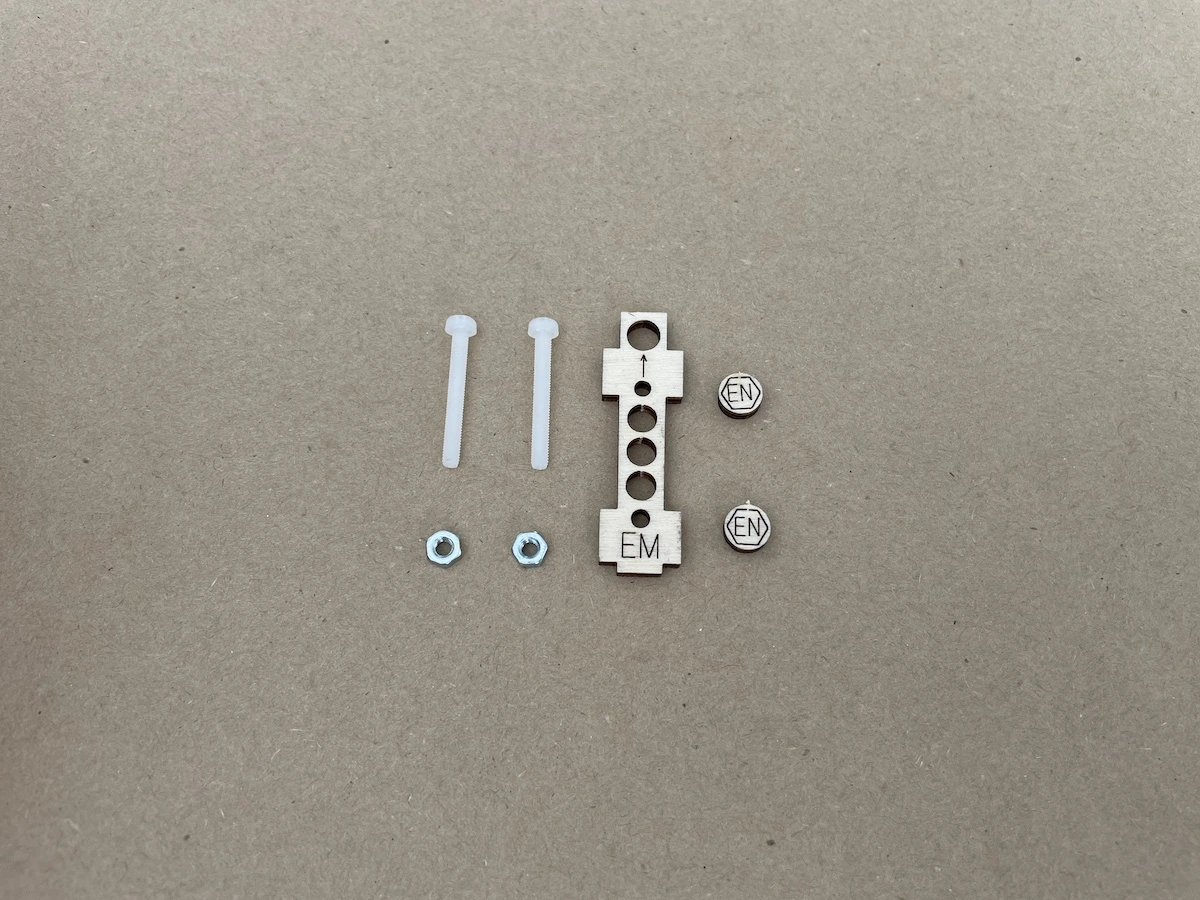
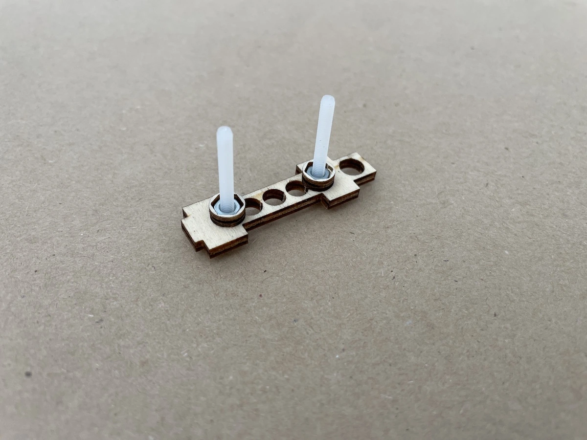

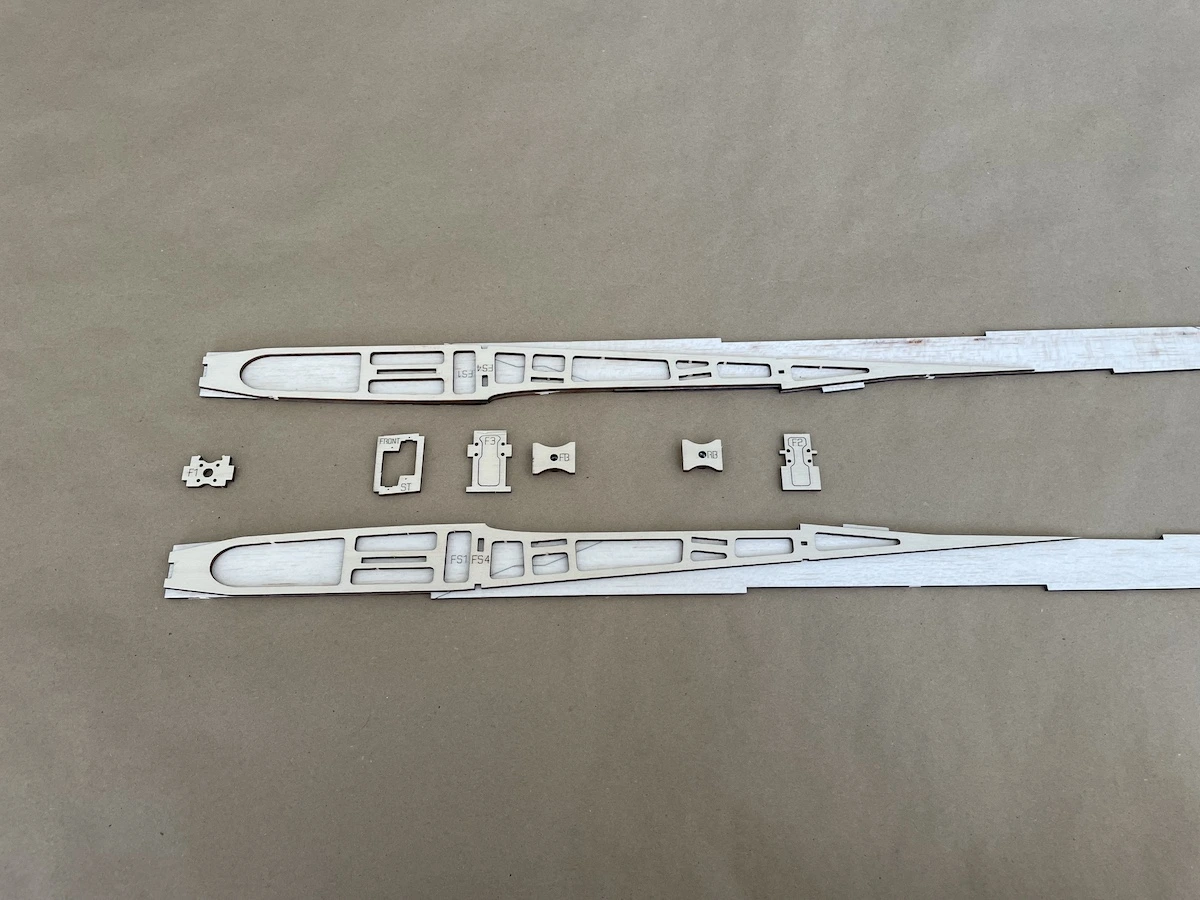
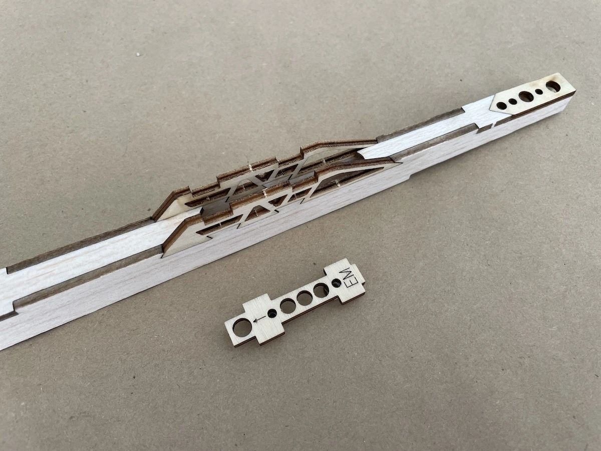
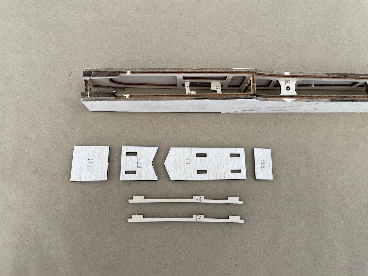
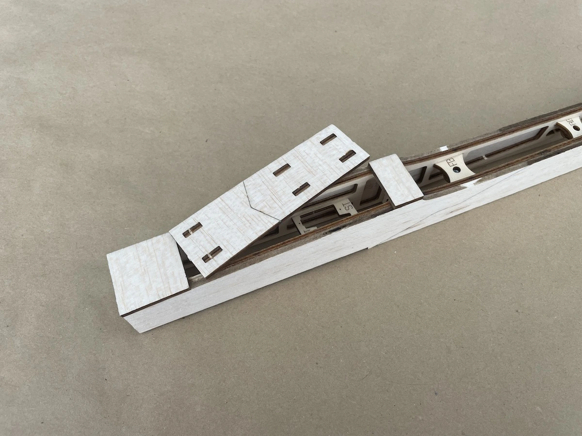
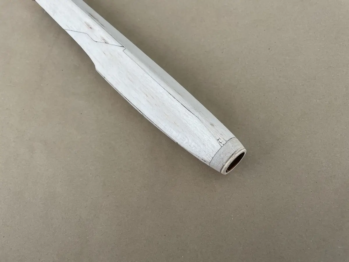
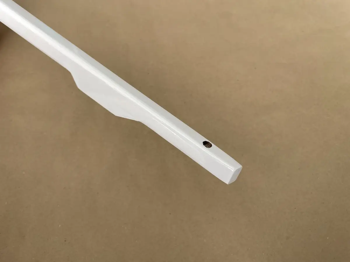
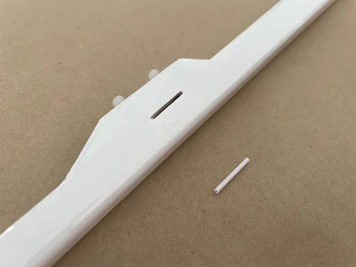
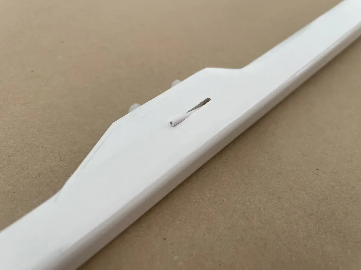
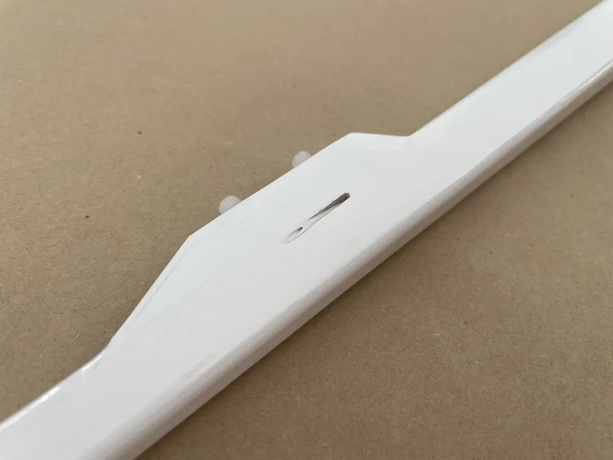
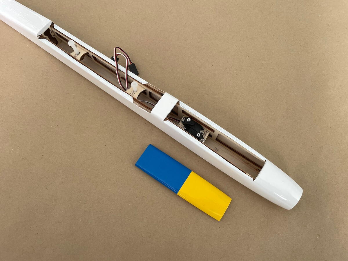
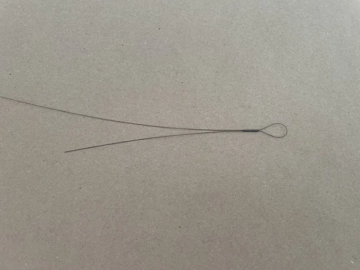
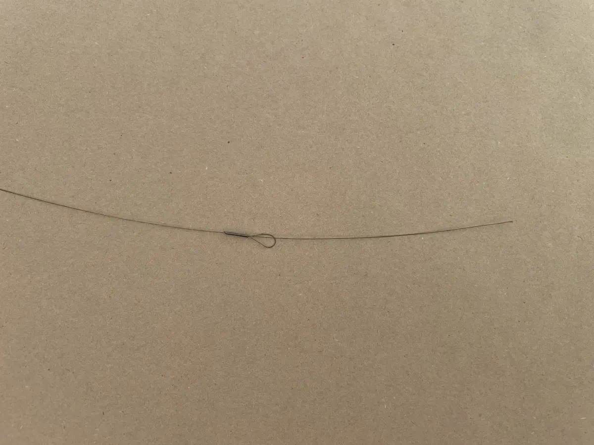
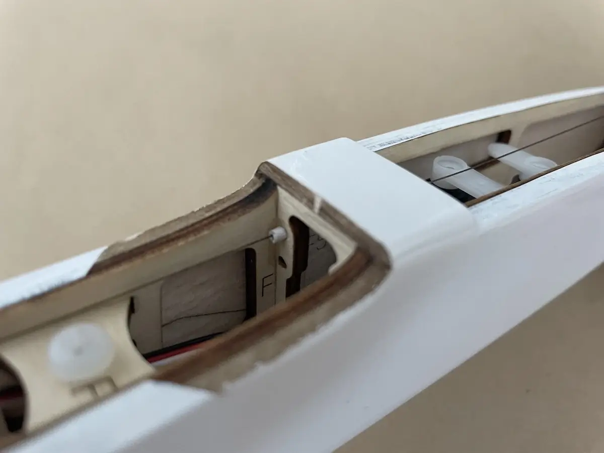
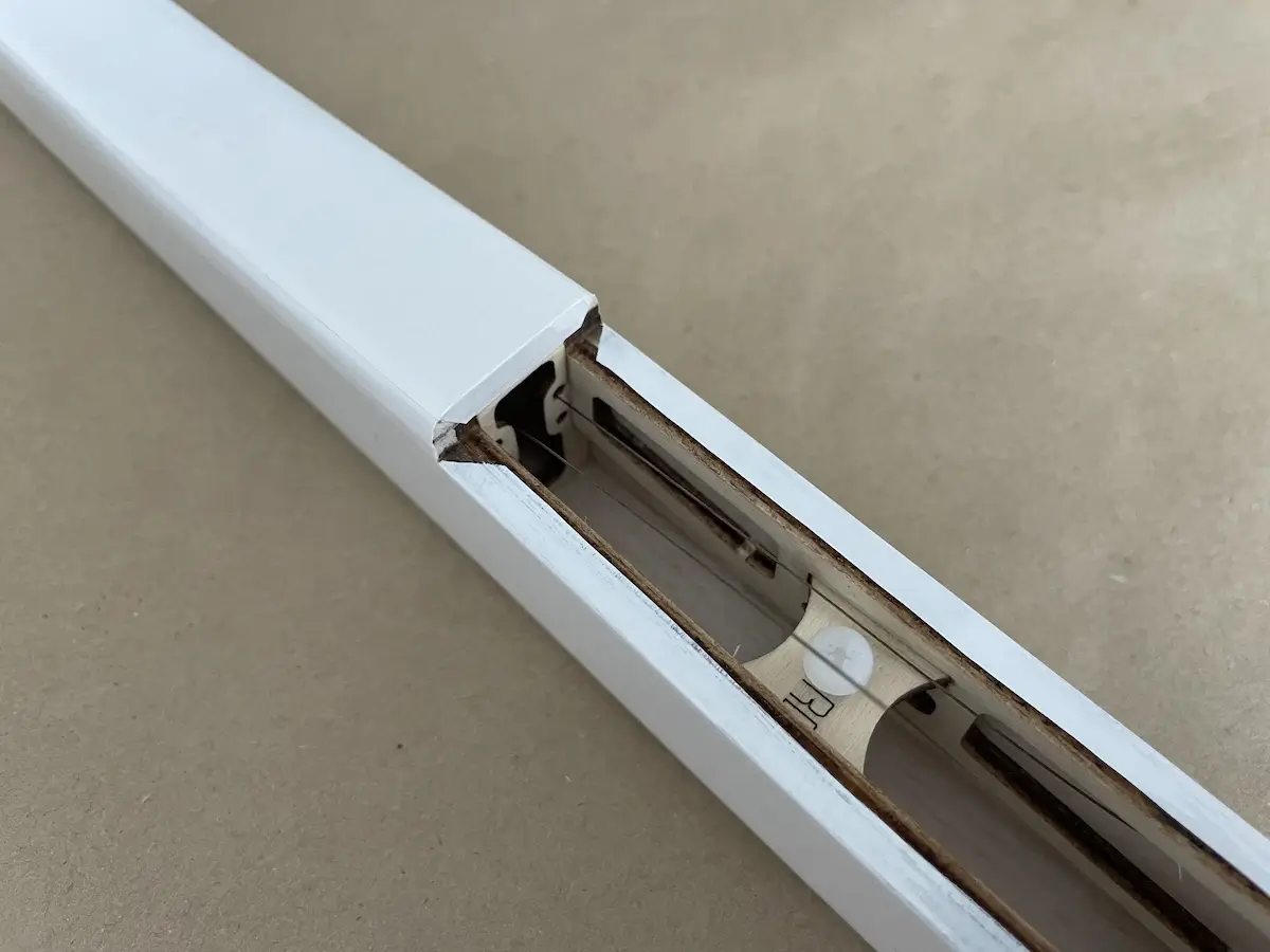
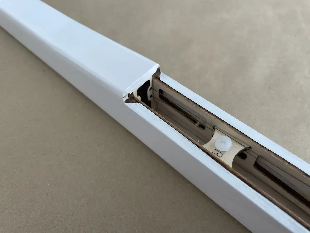
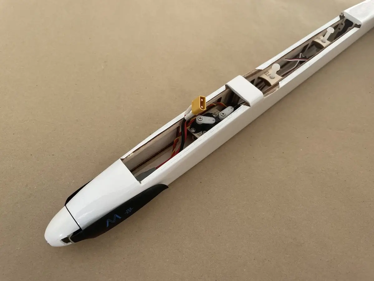
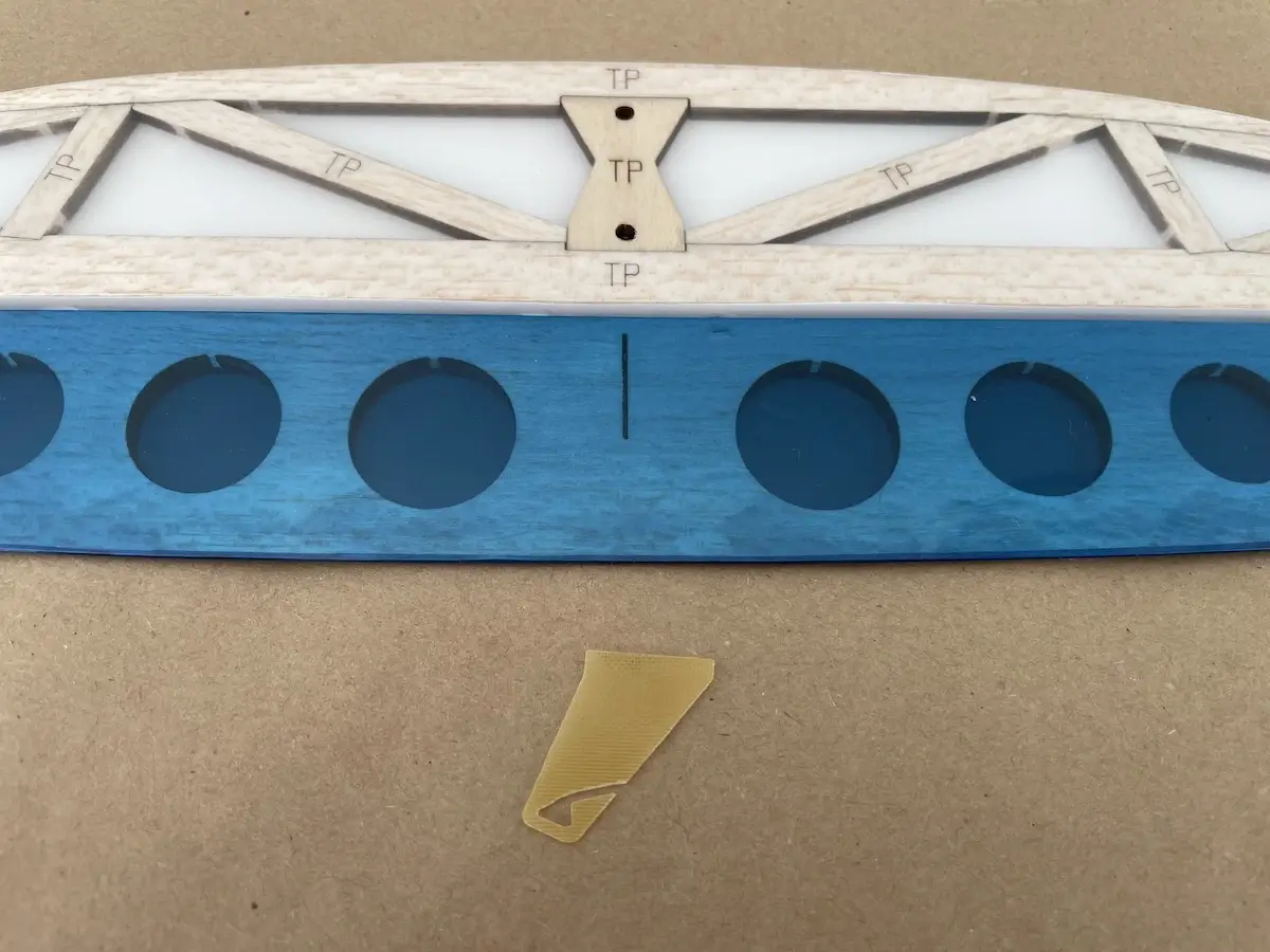
Pro Tip: make an O-ring to hold the hatch in place
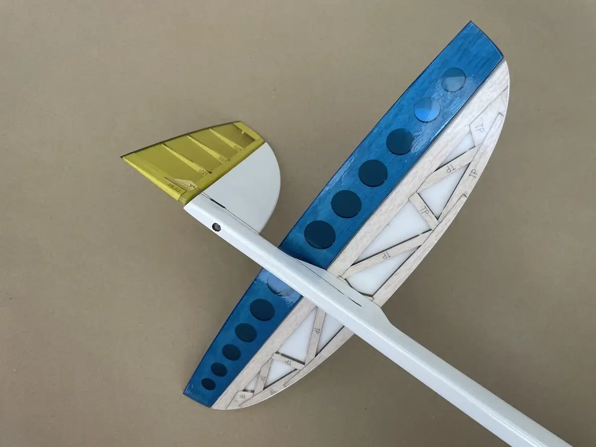
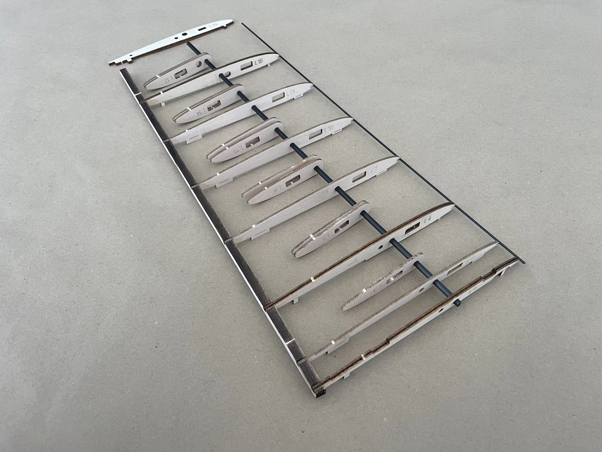
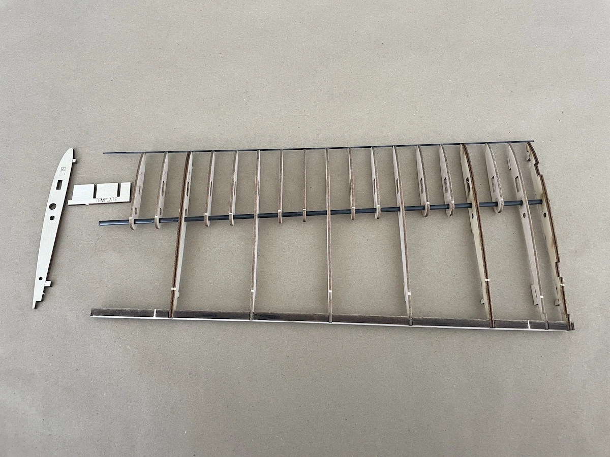
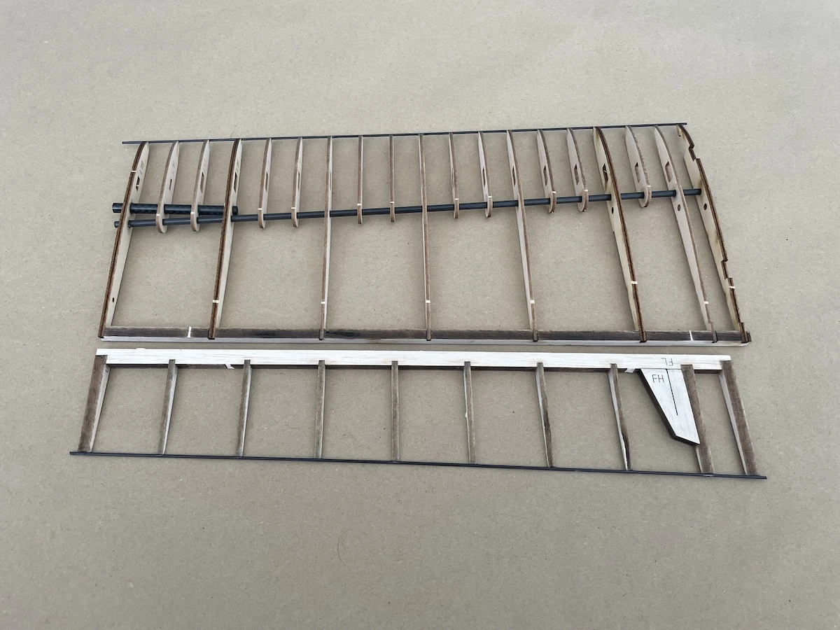
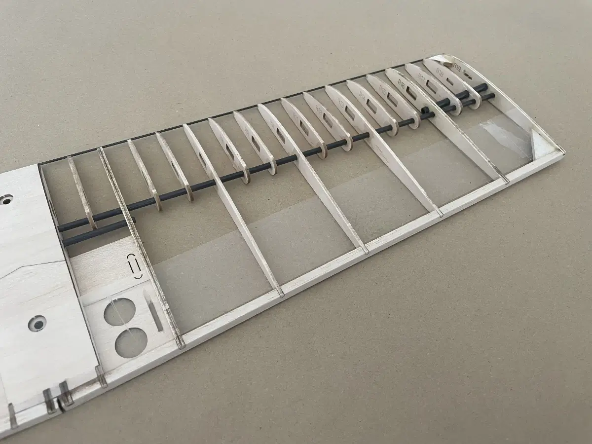
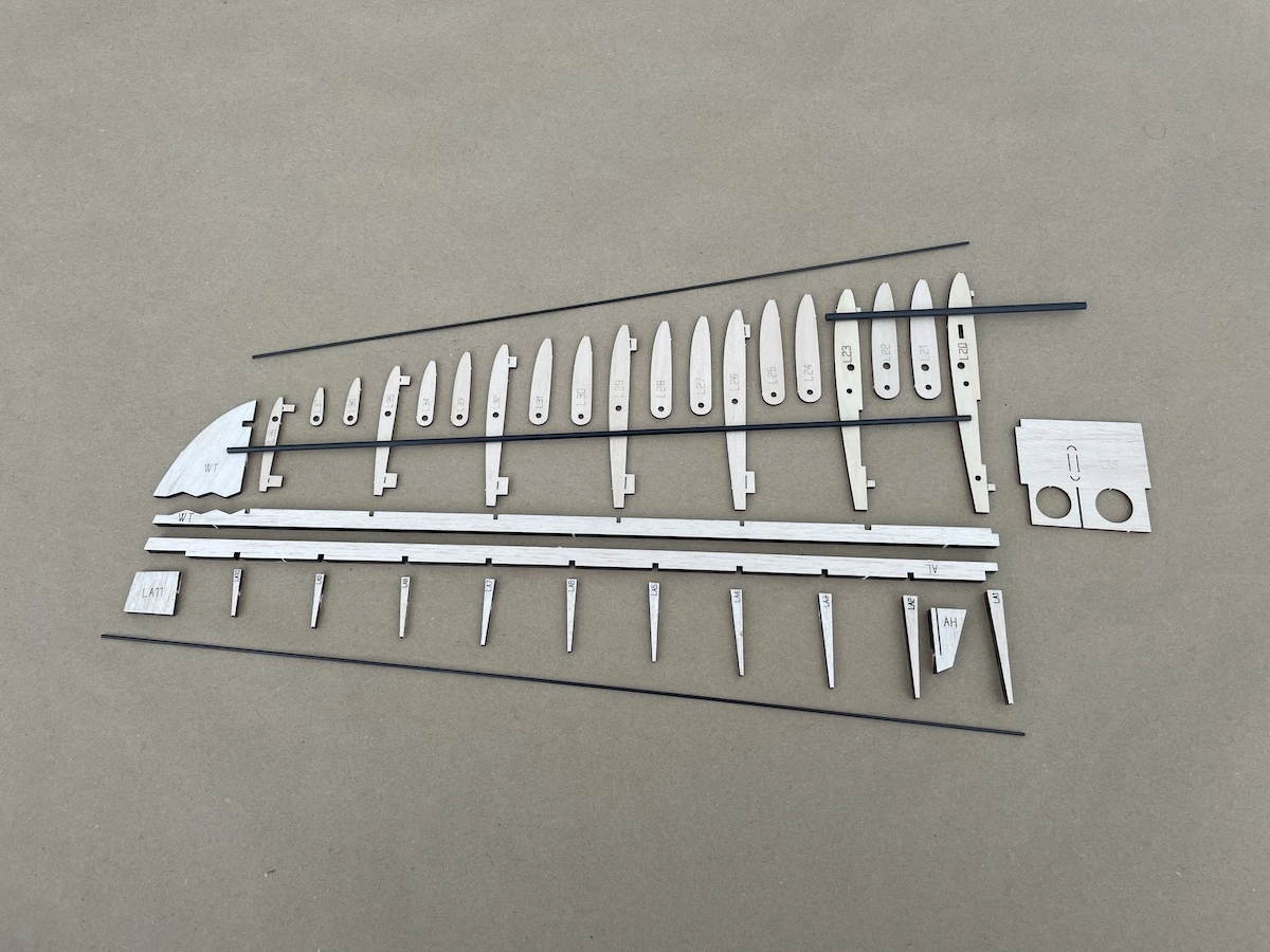
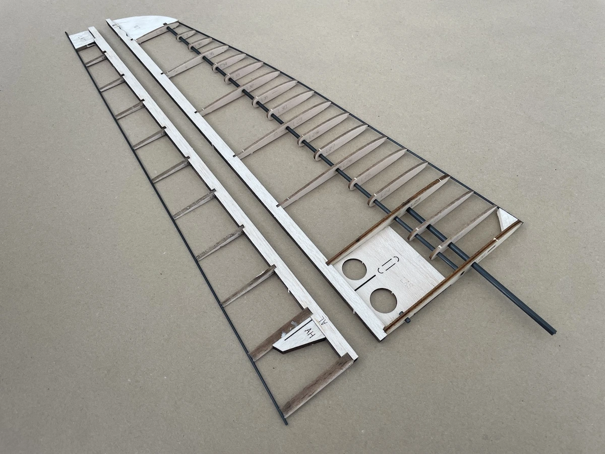
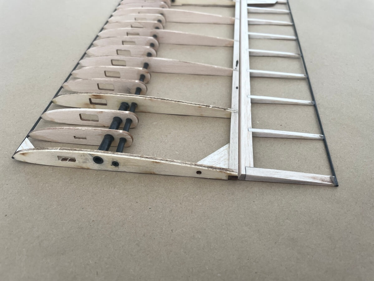
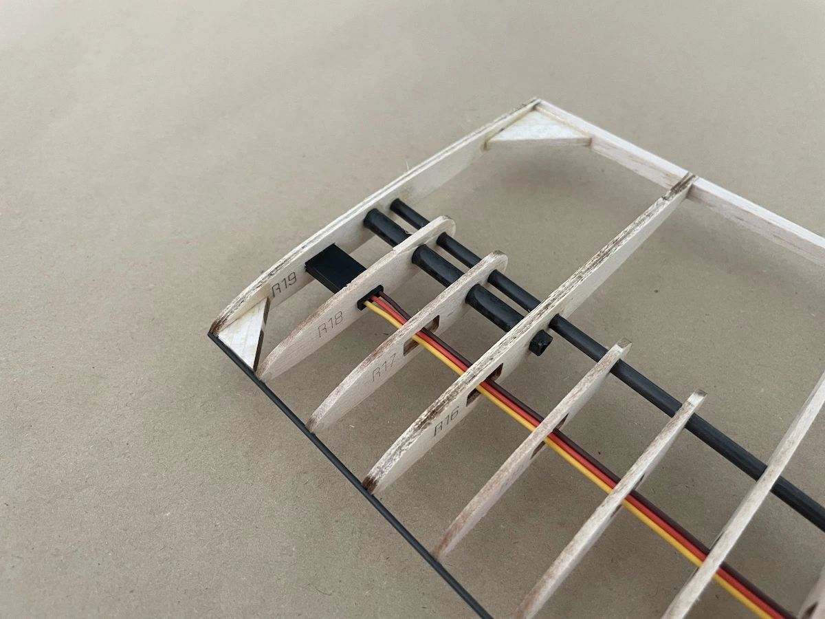
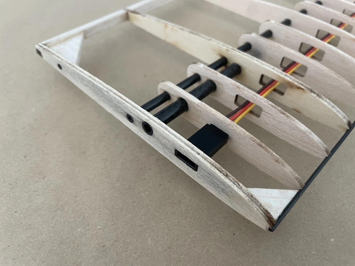
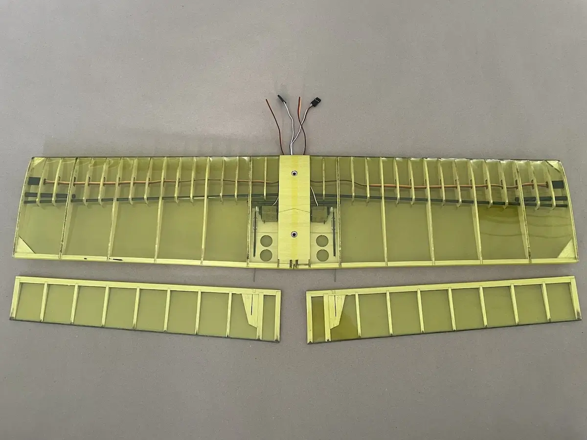
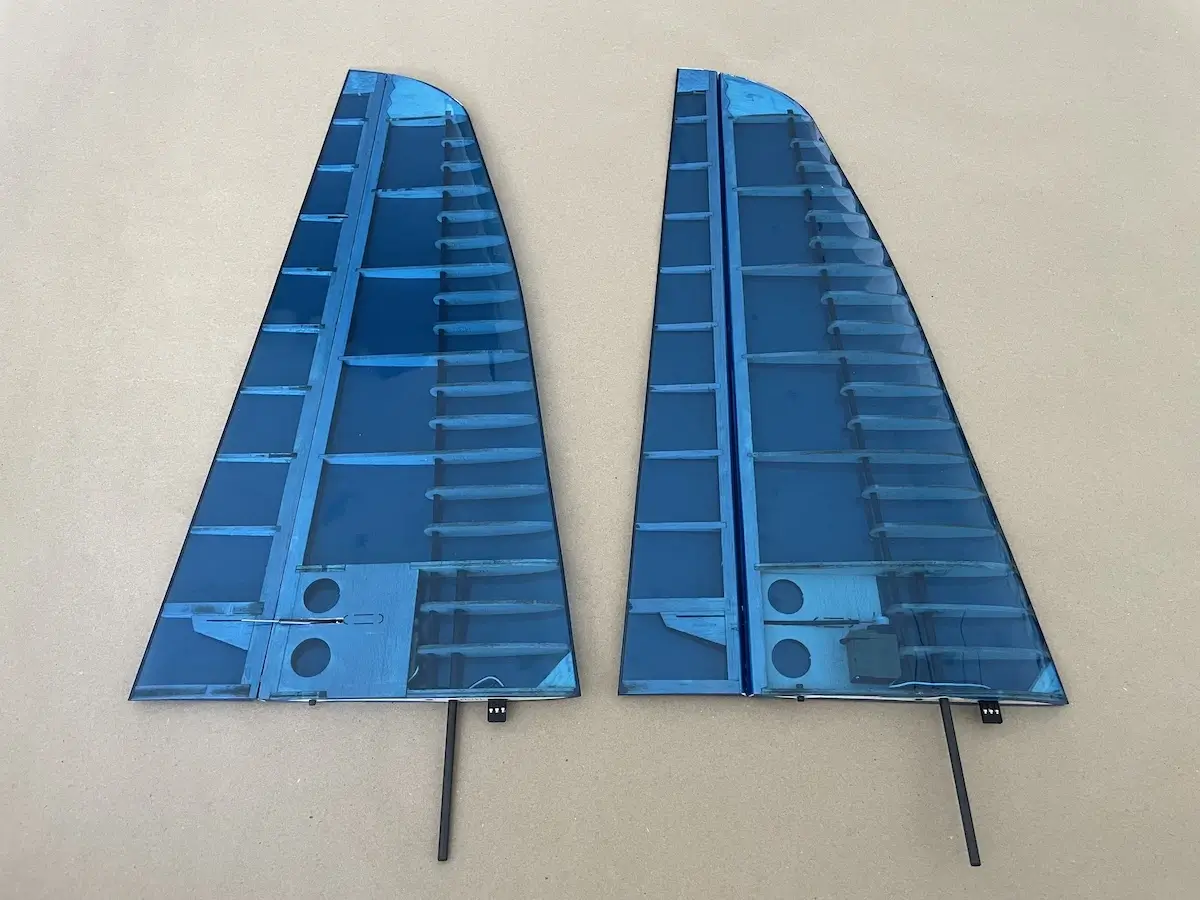
Part 3. Wings
Assemble your wing on a flat surface and use a printed plan provided with the kit for reference.
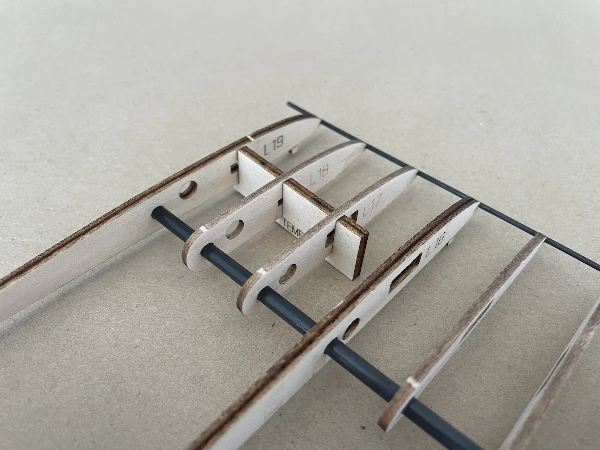
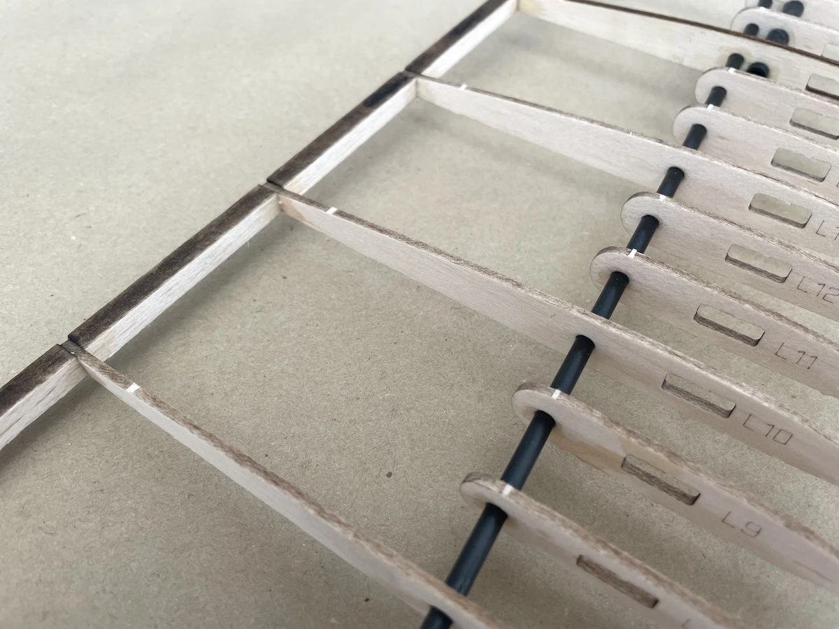
Wing ribs have tabs that ease up the build.
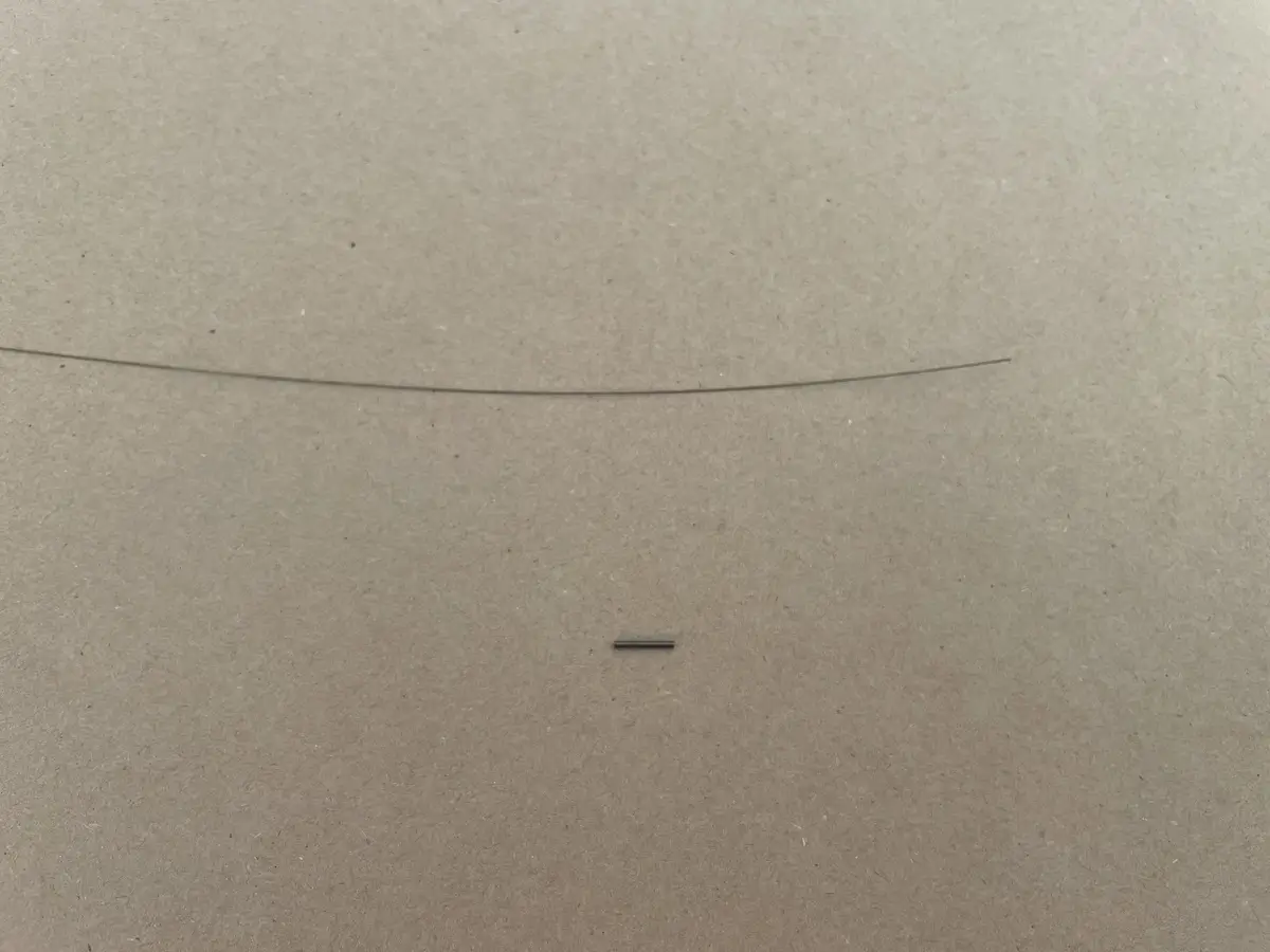
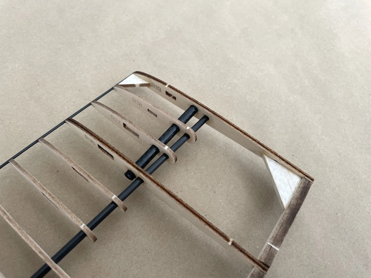
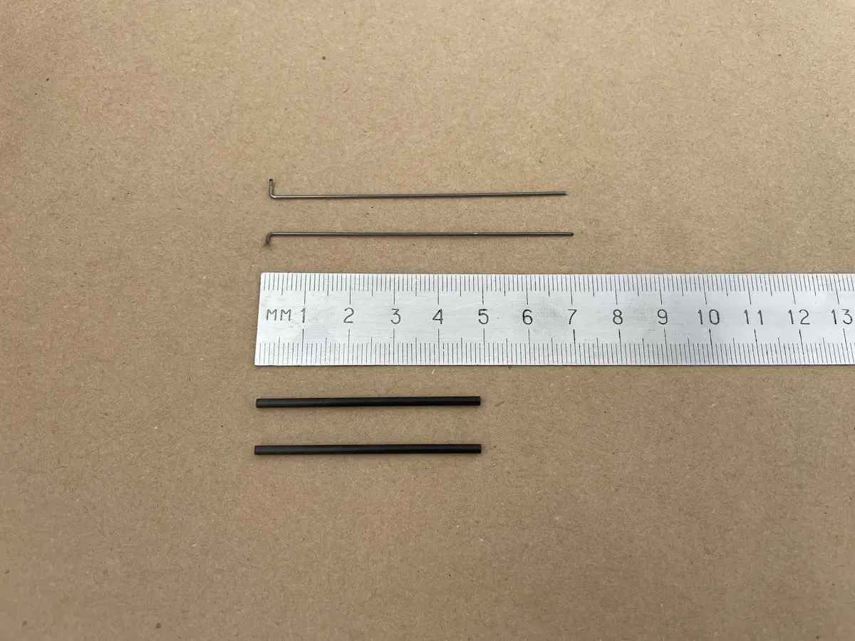
Before the wing assembly, take all 1.5mm CF rods and place them on the plan to identify the places where they should go.
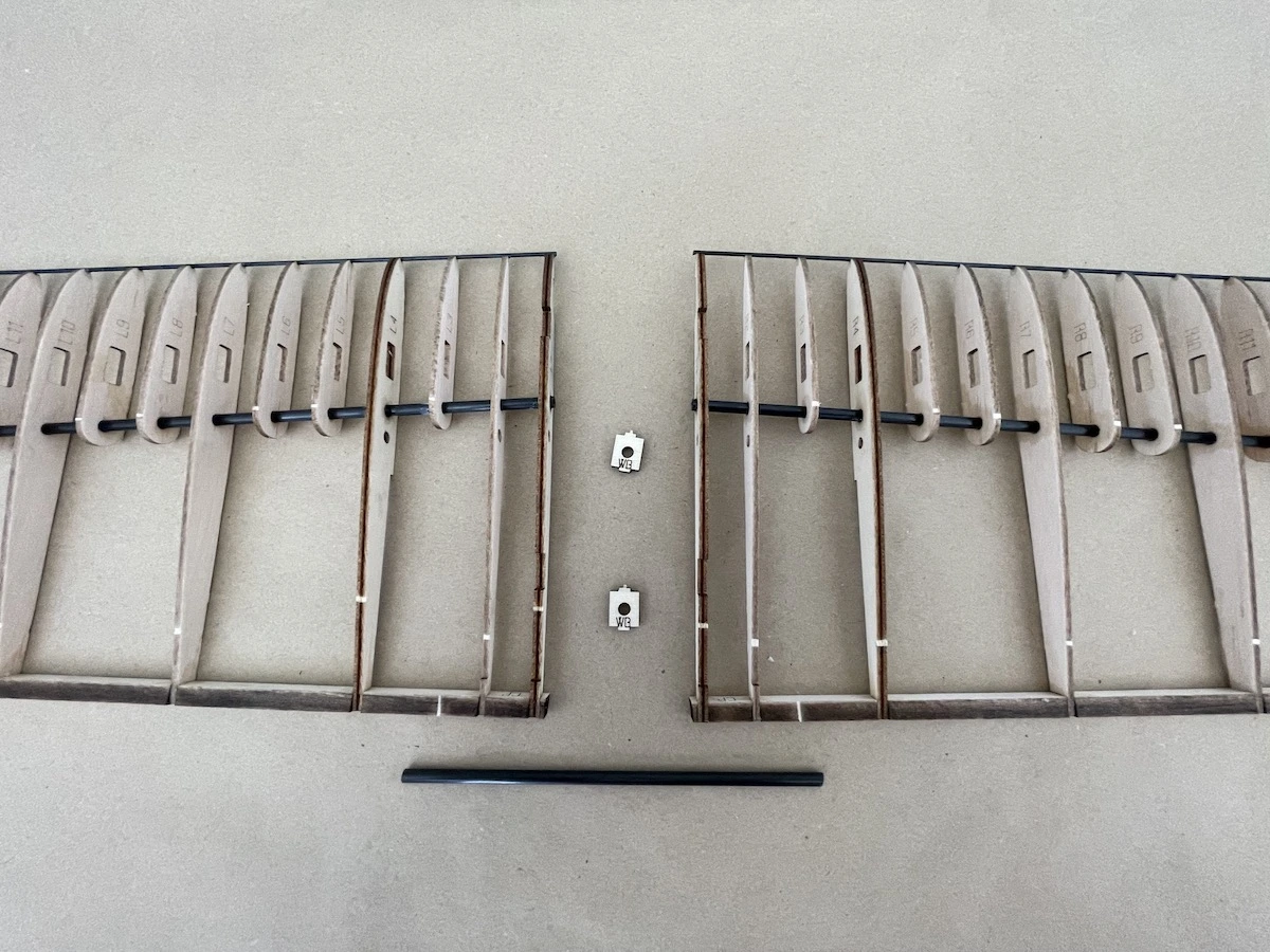
Note: the early kits used to have a 4mm spar in the central panel construction that was updated to 6mm in the most recent ones. This guide highlights the assembly of the early kit, so don’t be confused with the thinner spar in the pictures below. The rest of the construction is 100% the same.
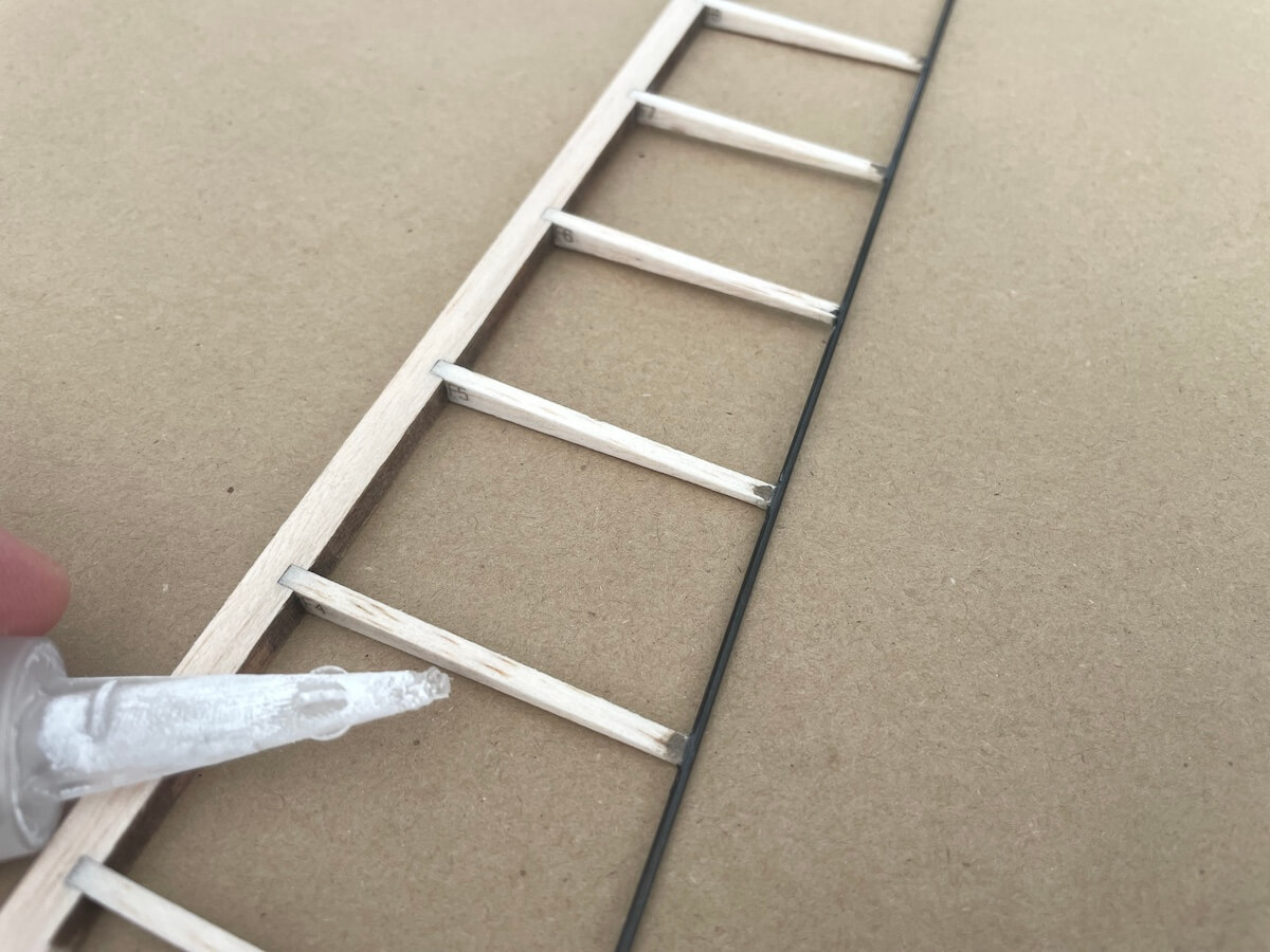
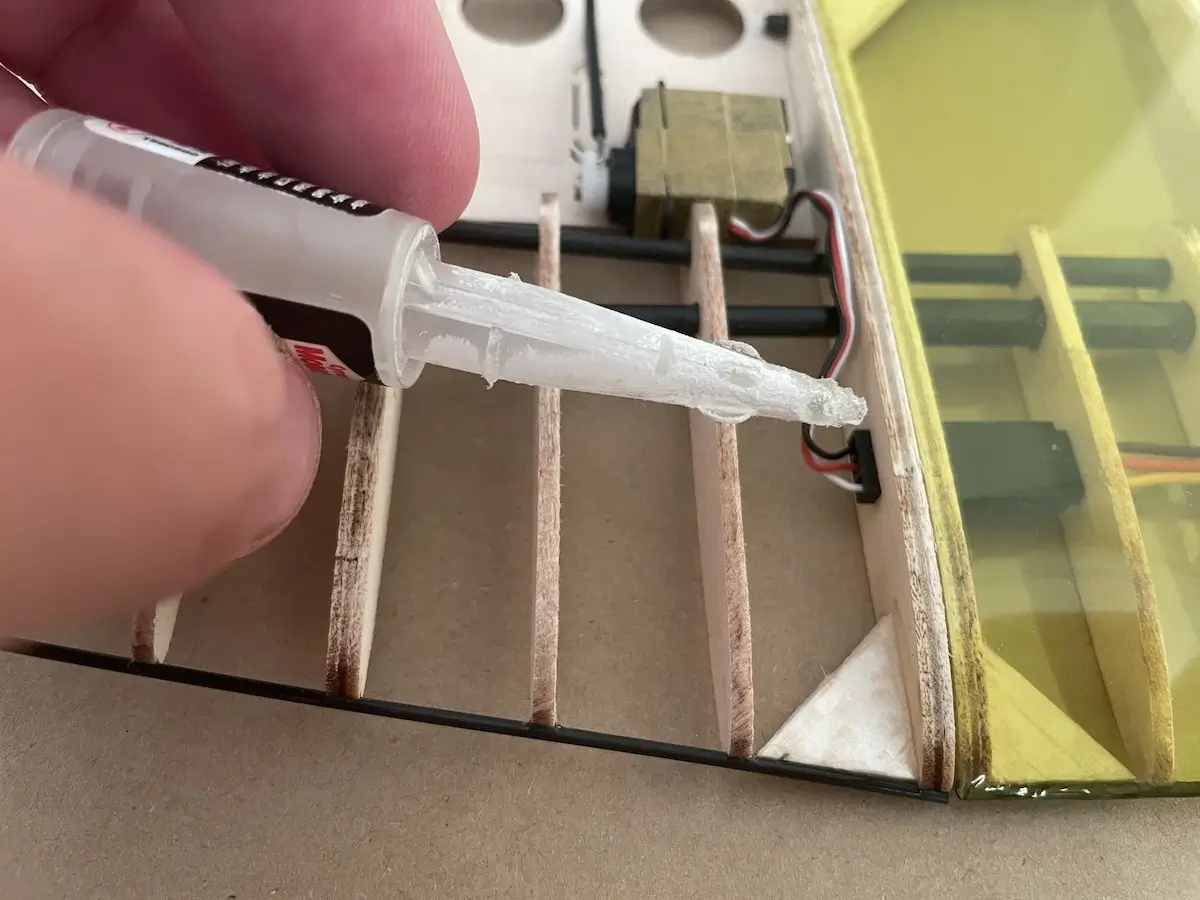
Pro Tip:
After assembling the flaps and ailerons, use a drop or two of thin CA glue to «soak» the 3mm balsa ribs from the CF leading edge to approx. half of their length.
This will prevent ribs from cracking under the tension of the covering film and will produce a better covering experience overall.
Important!
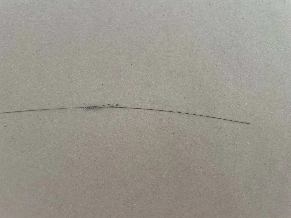
Your kit contains ~130mm long twill 6x4mm carbon tube. This should be cut in half and used as a sleeve tube for the wing joiner where the wing tip connects to the central panel. A connection in the middle of the central panel should use a part of a pultruded 6x4mm carbon tube instead.
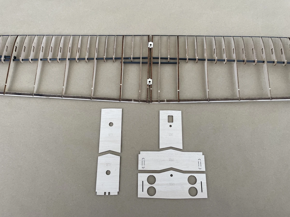
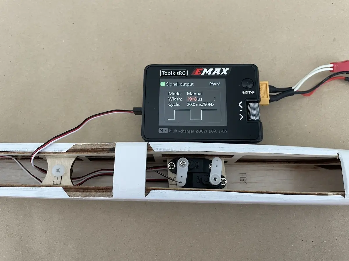
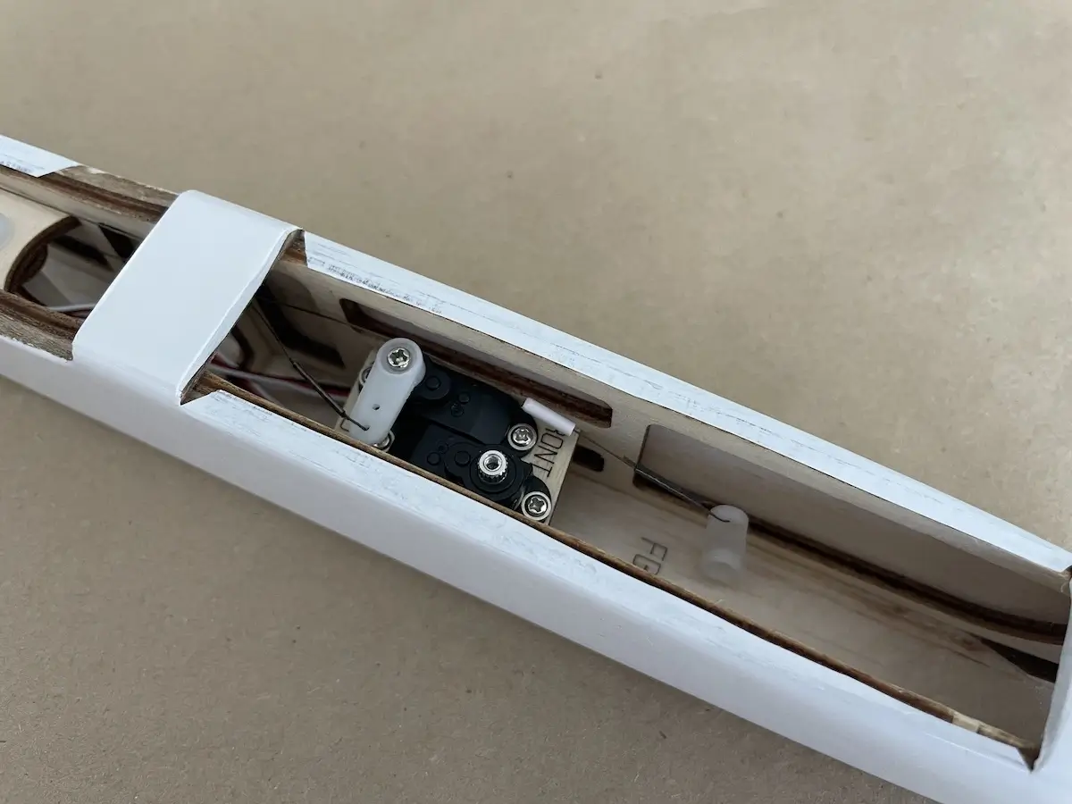
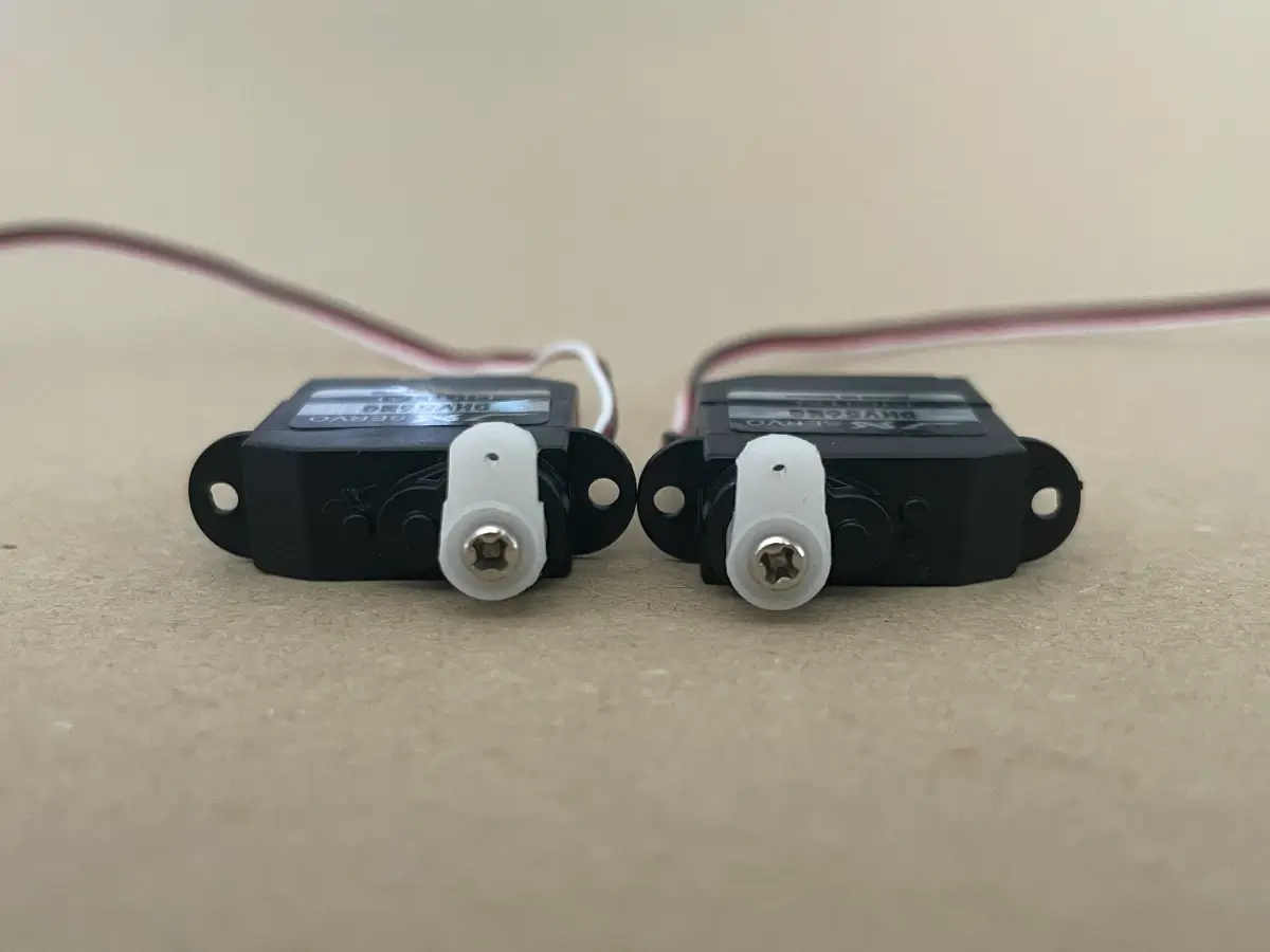
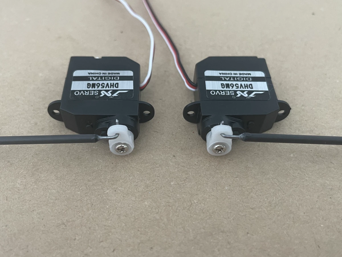
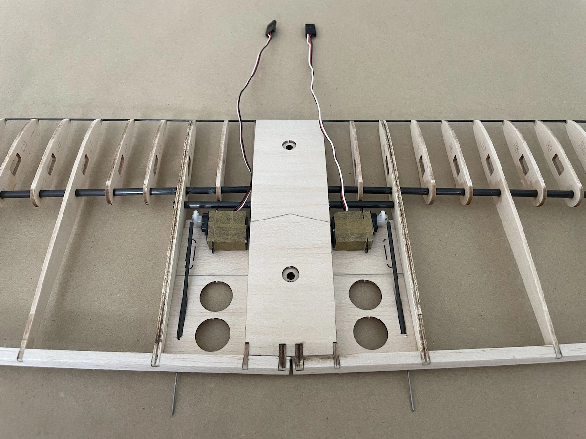
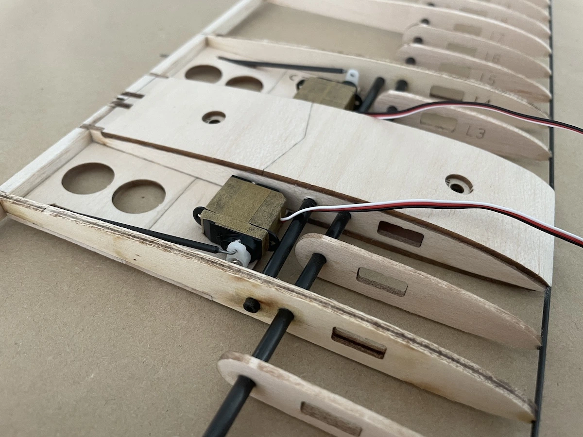
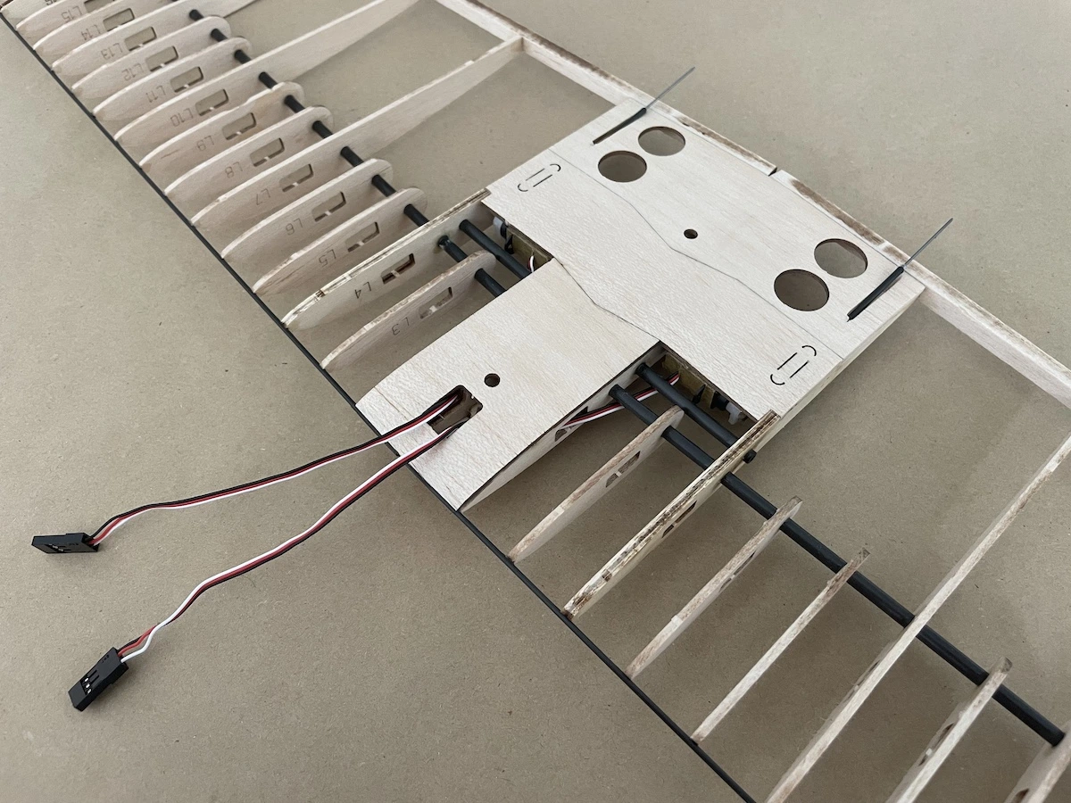
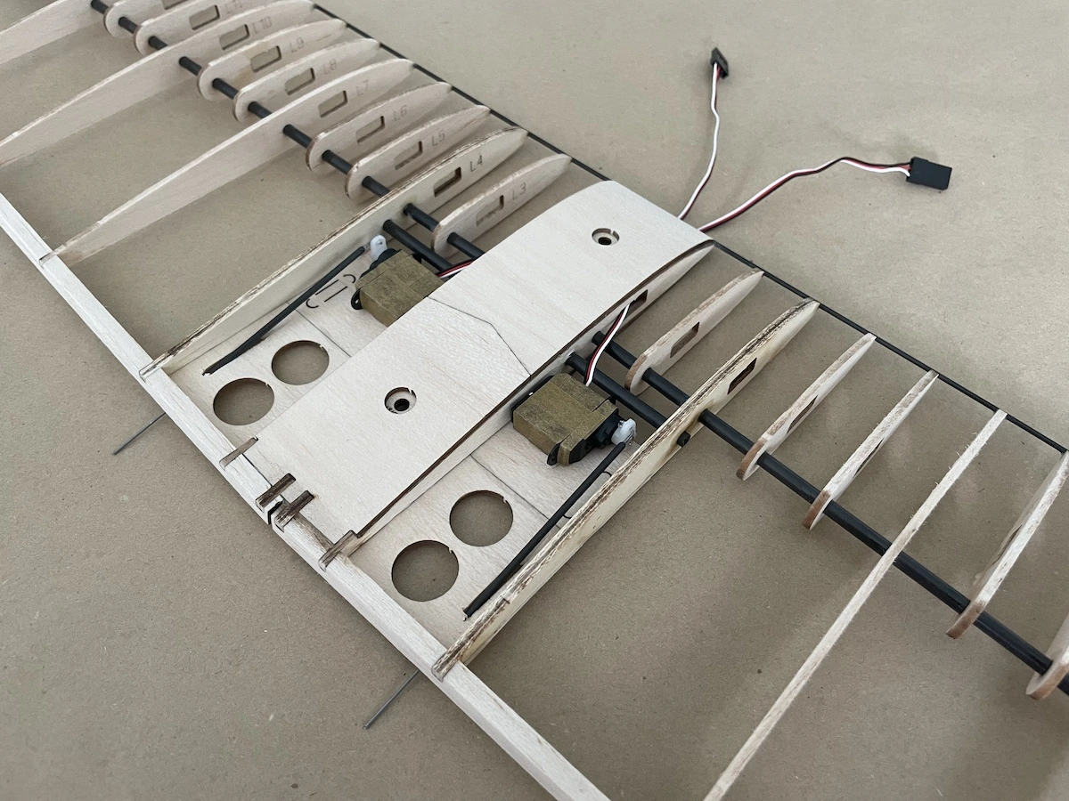
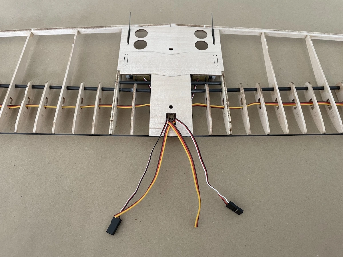
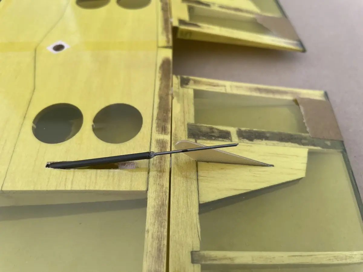
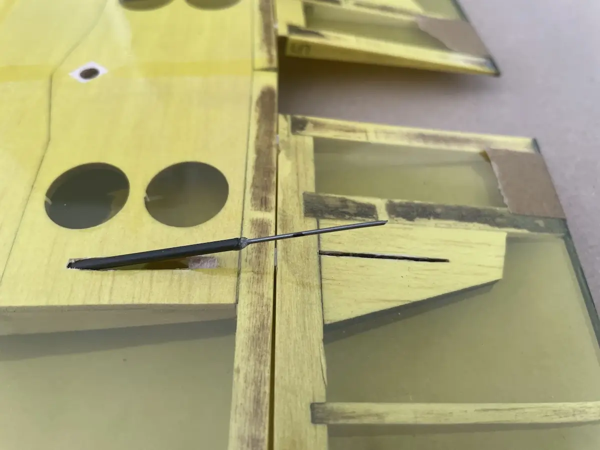
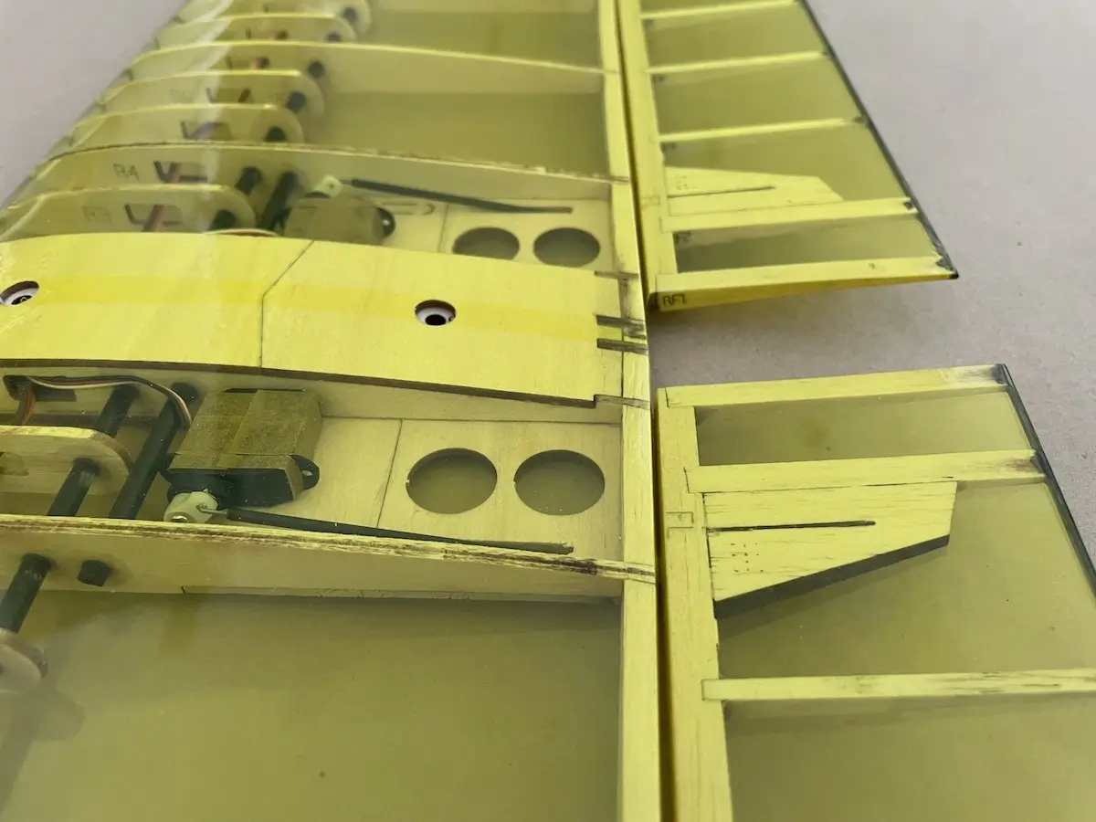
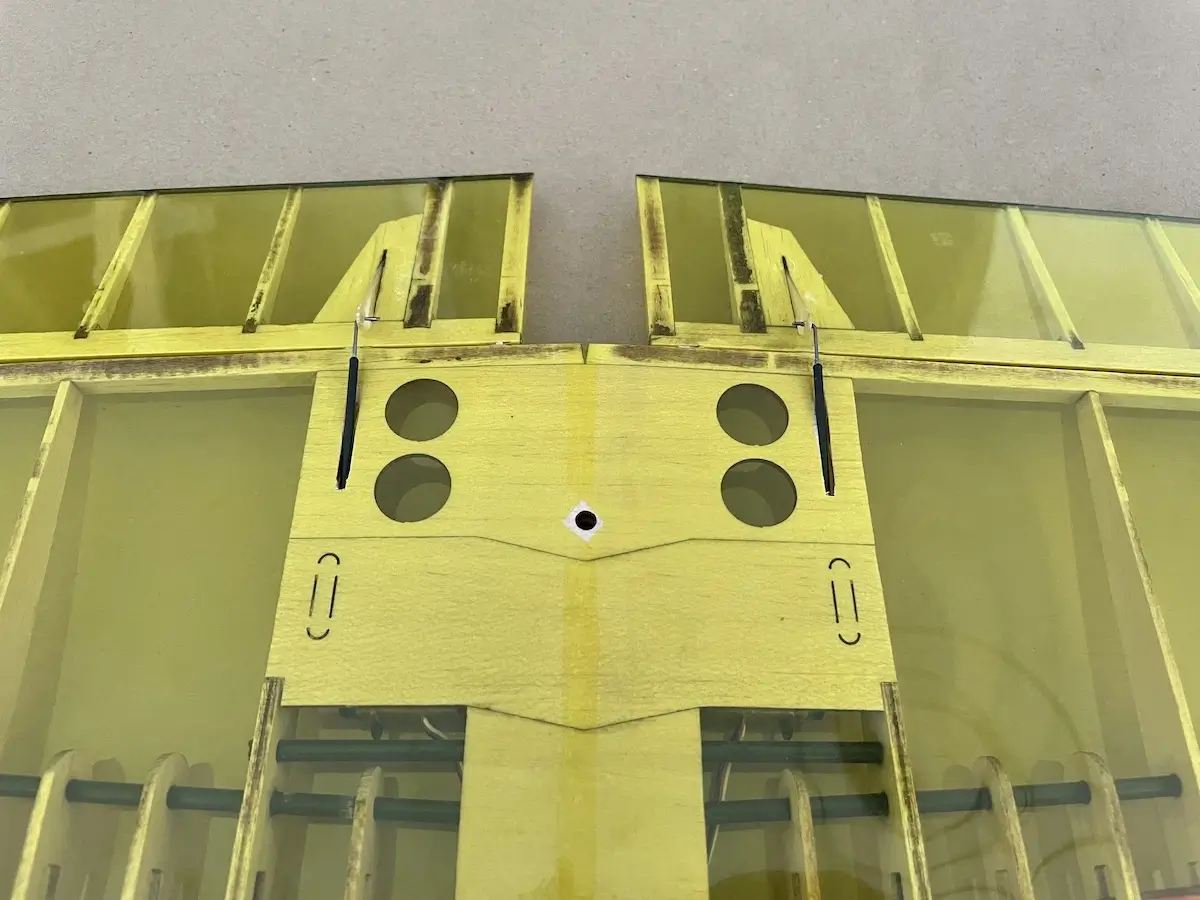
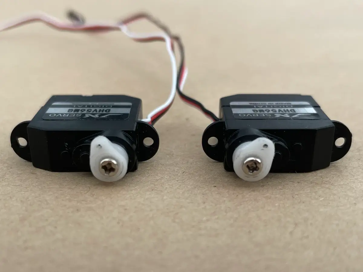
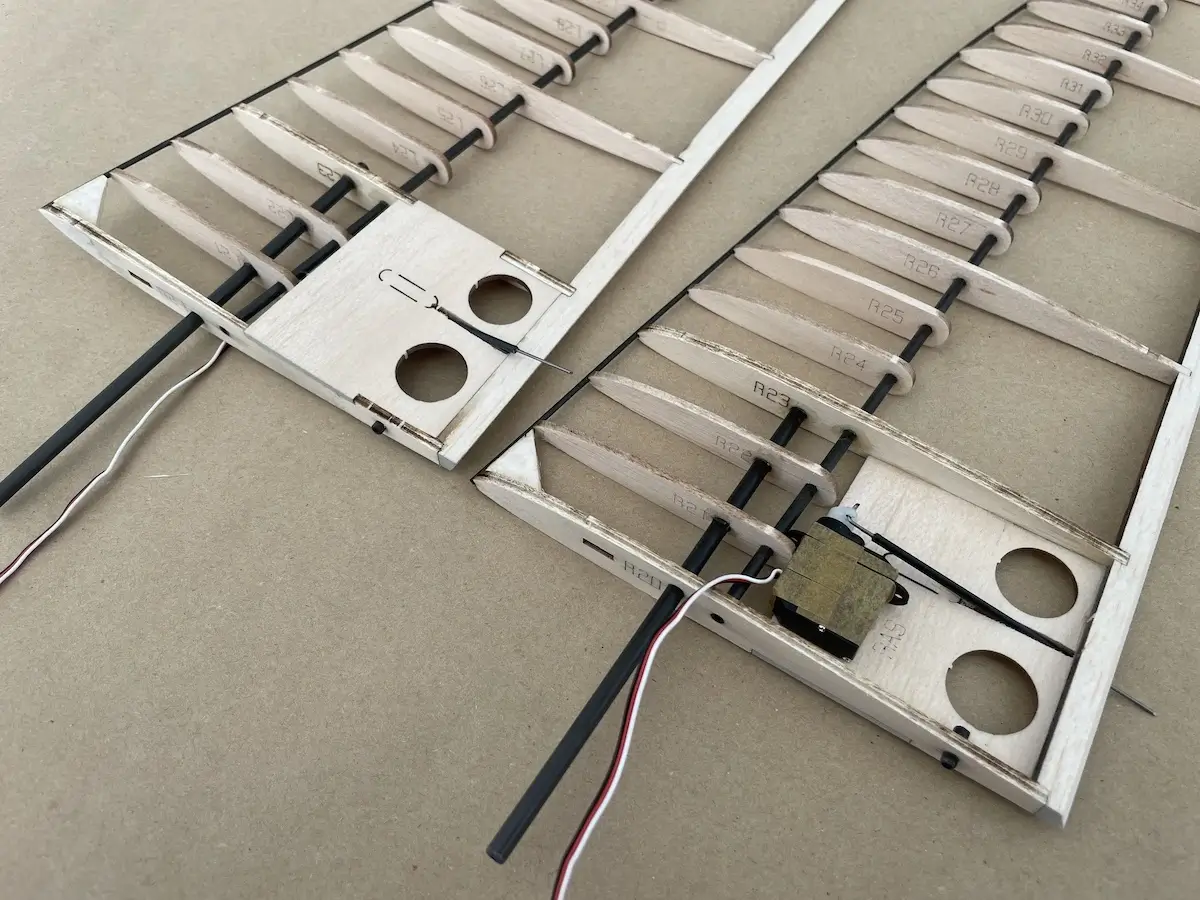
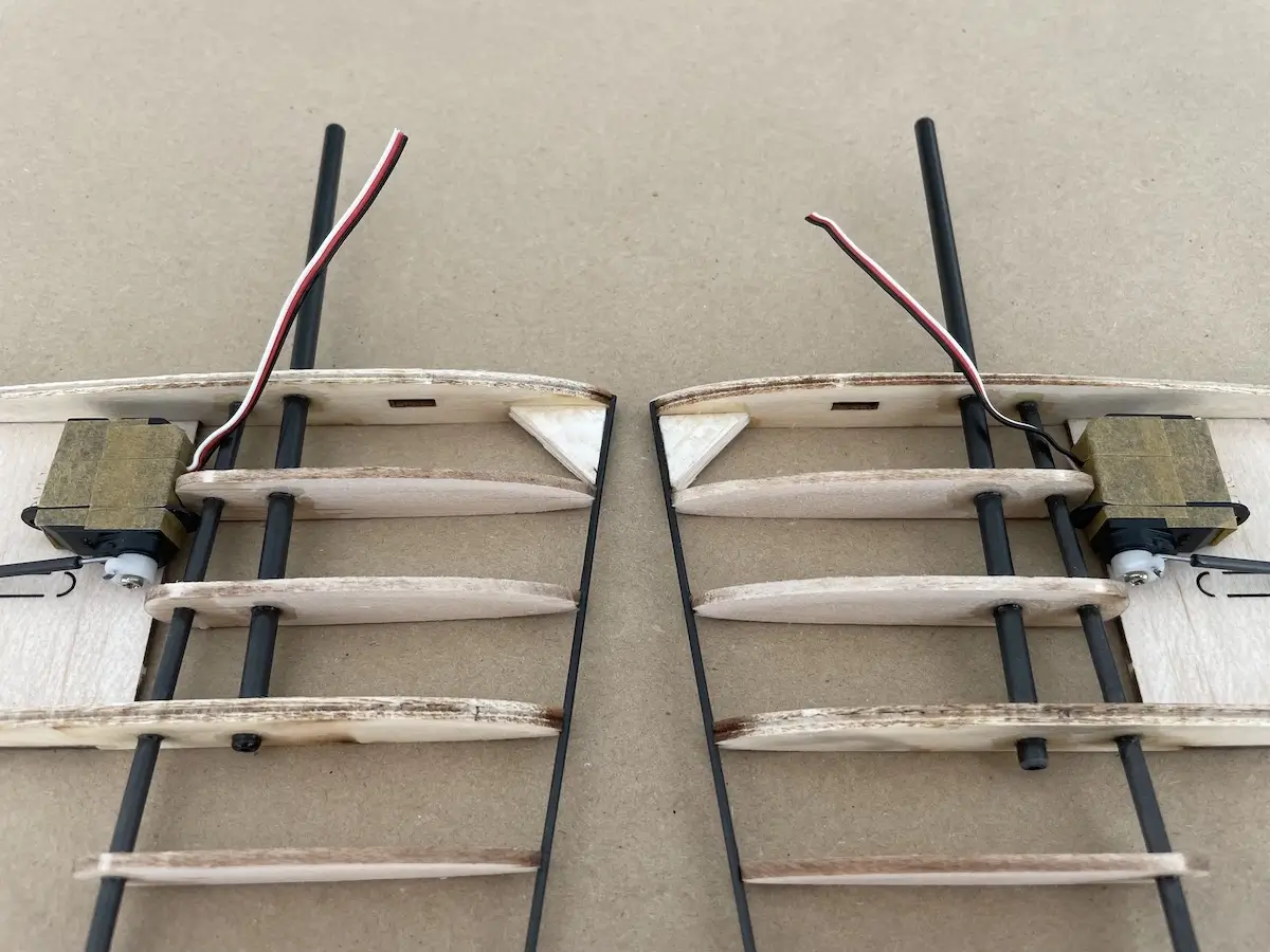
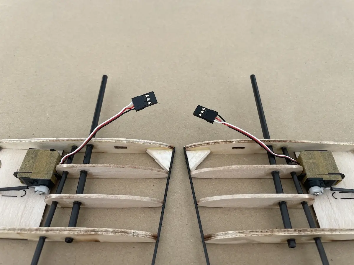
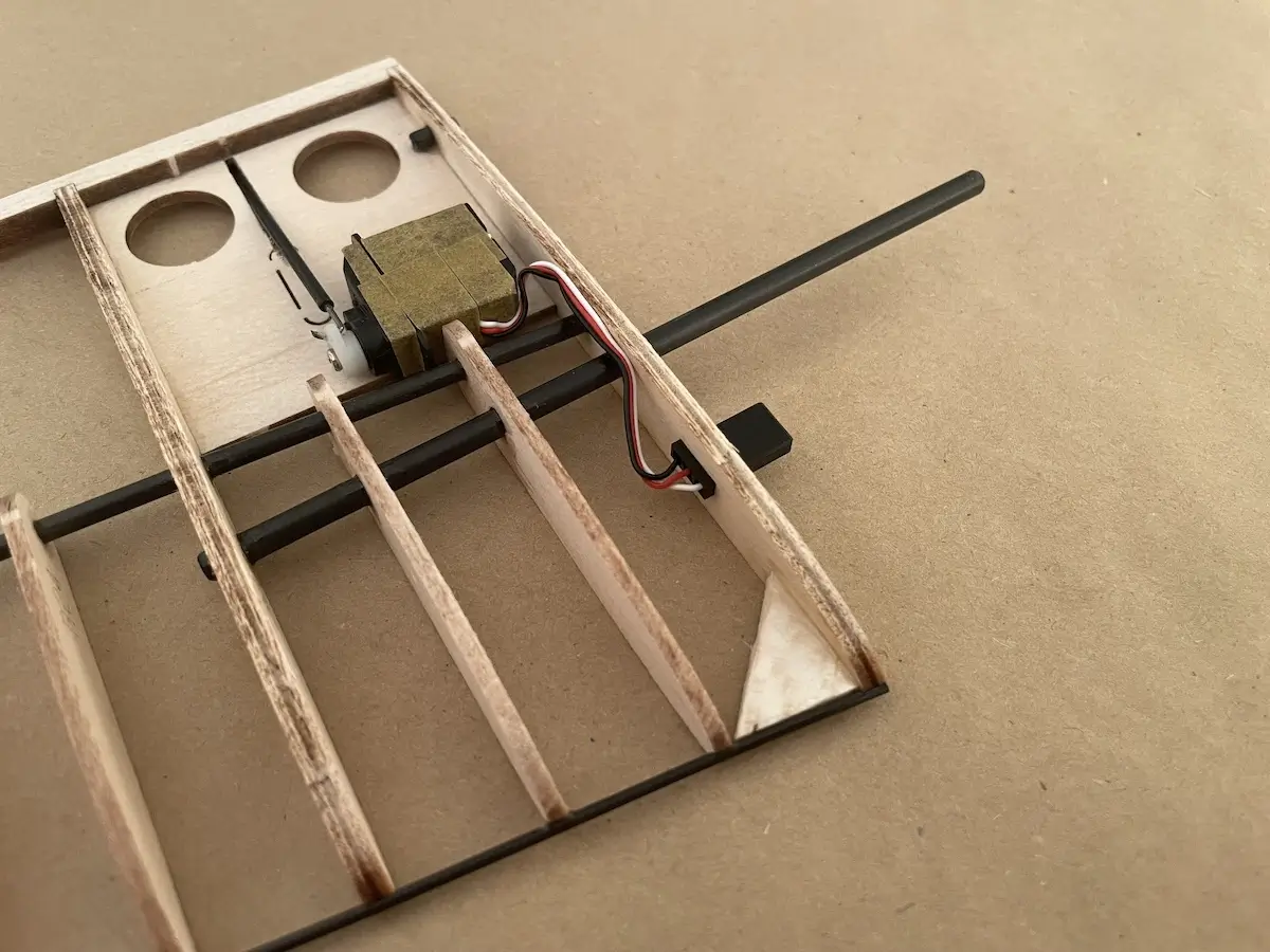
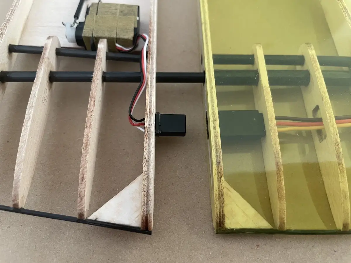
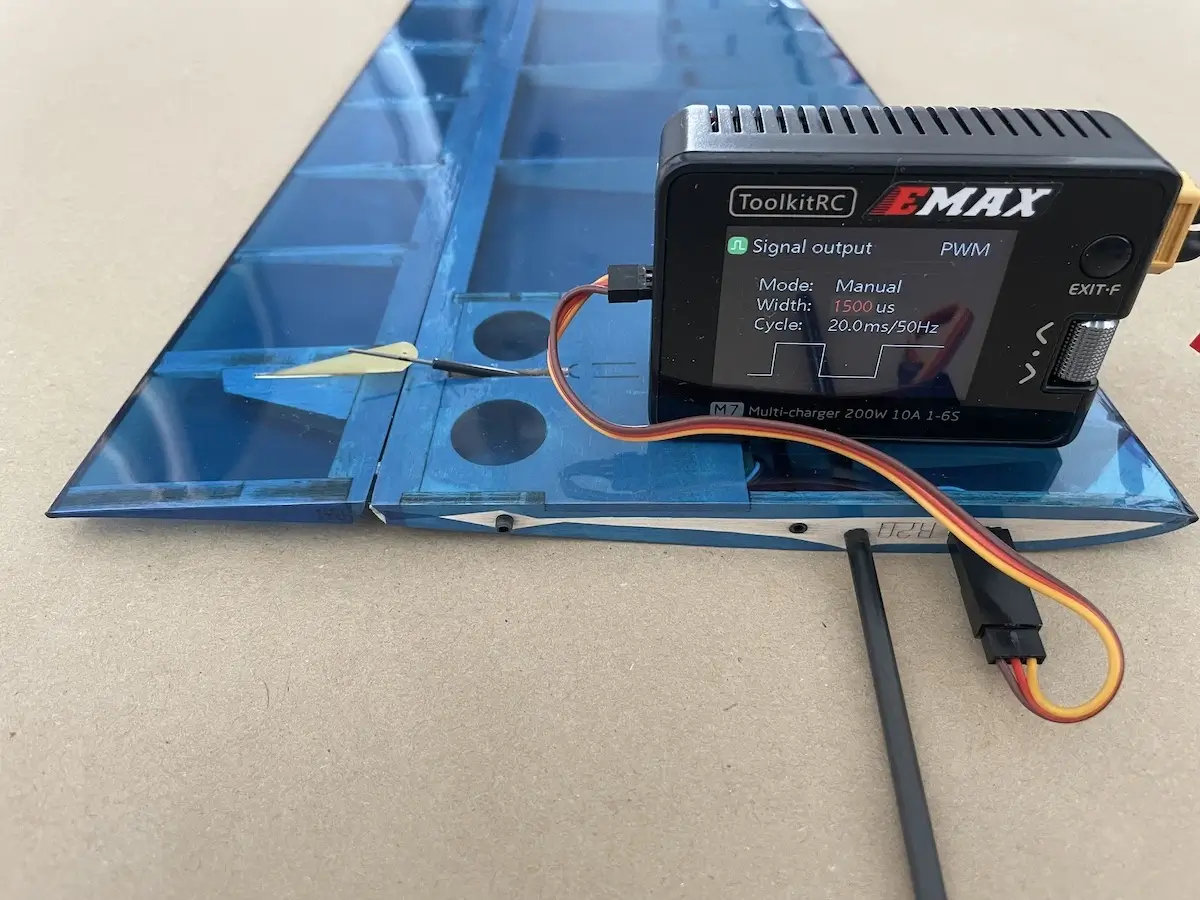
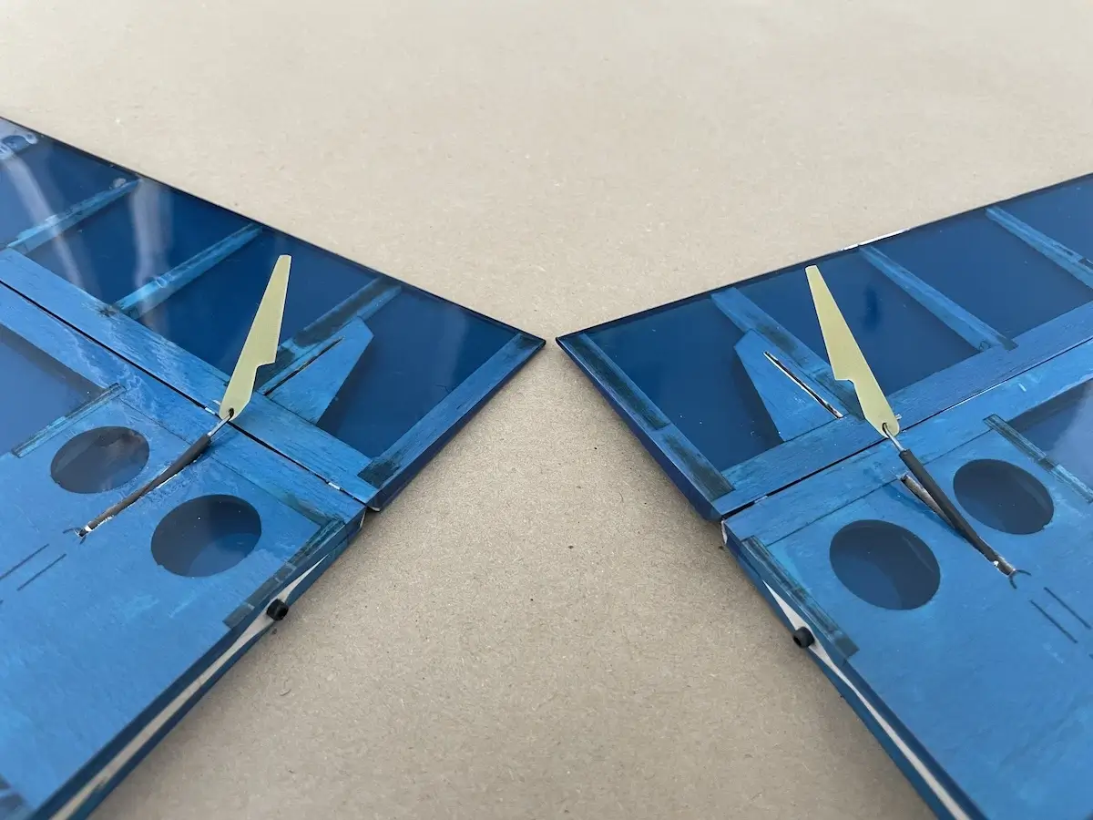
Part 4. Wing Servo Installation
Pro-Tips:
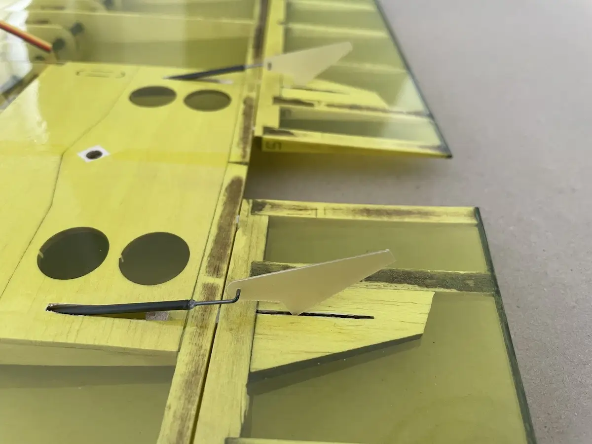
- The «default» servo installation uses small servo arms that hide under the wing covering. Drill the aileron servo arm as close to the horn basement as possible. In most cases, for the flap servo, you can use the first hole, closest to the center.
- Make sure that the servo horn can move freely under the future covering.
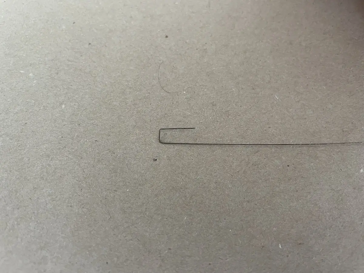
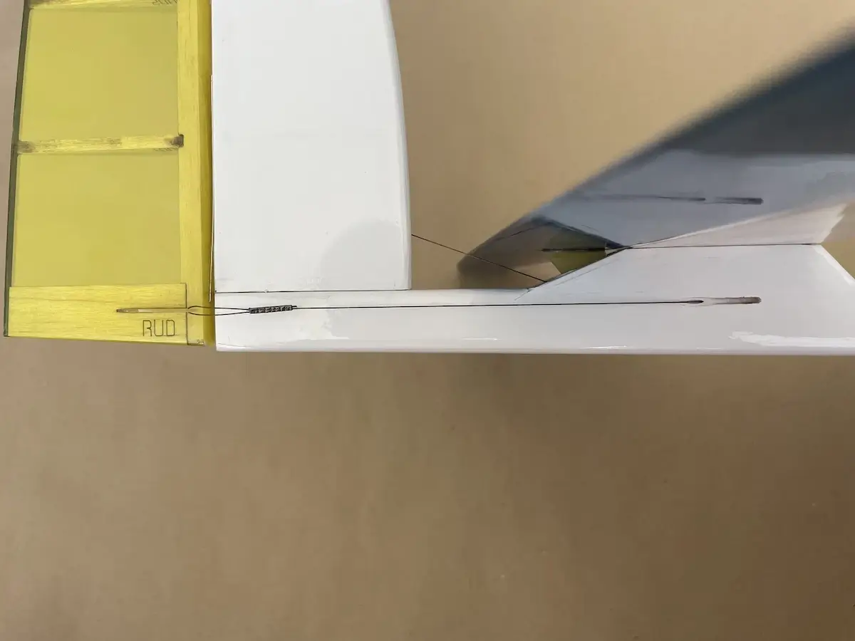
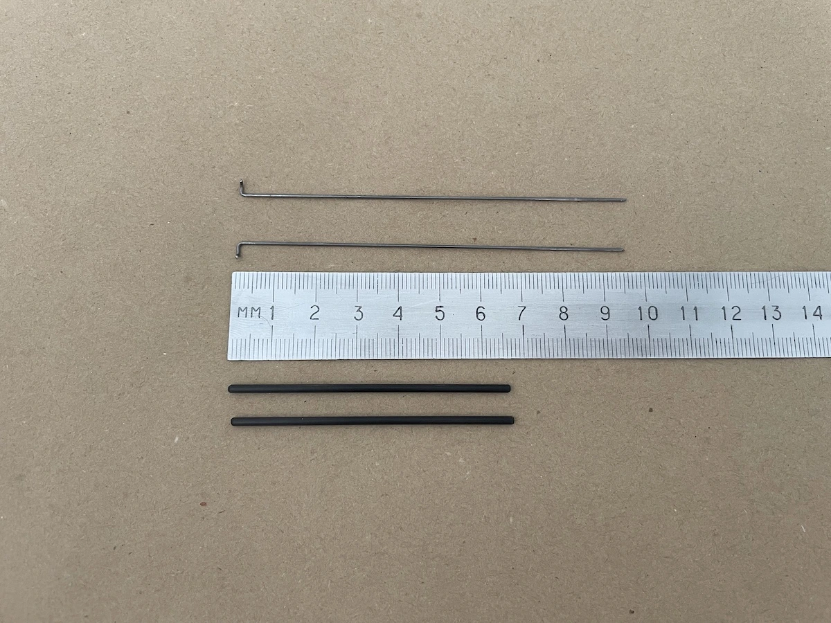
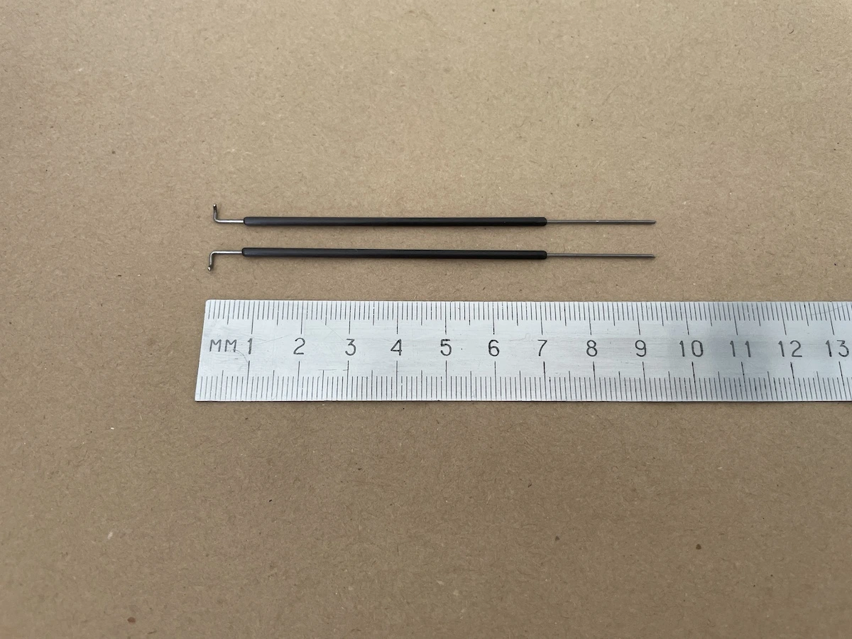
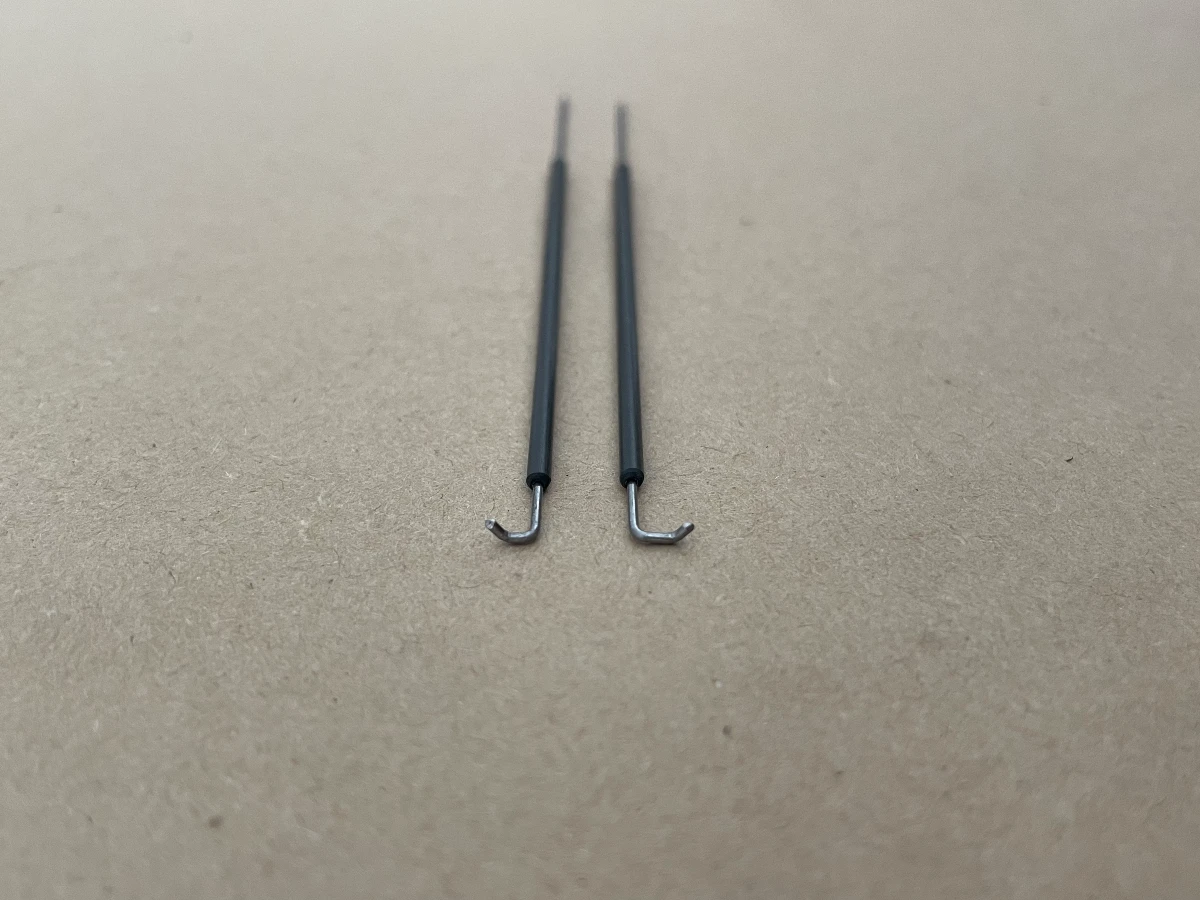
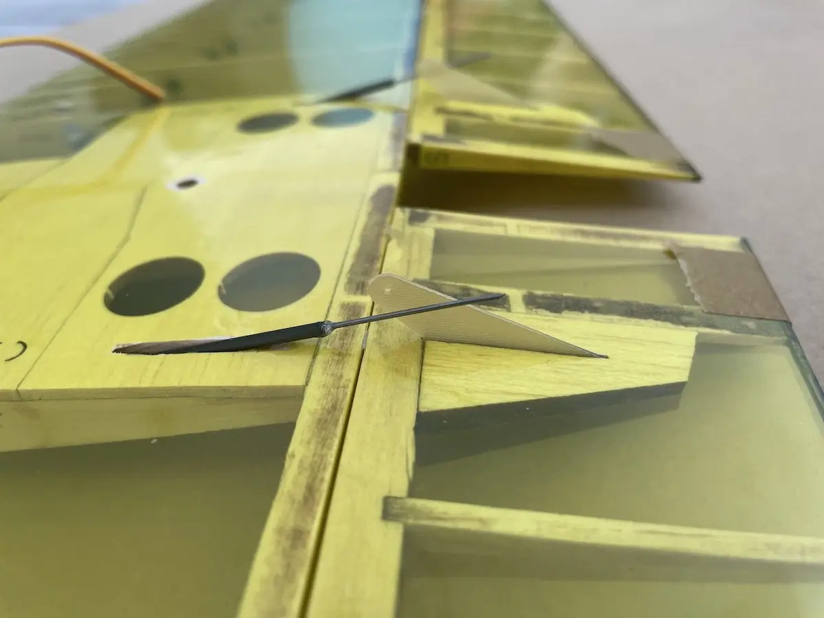
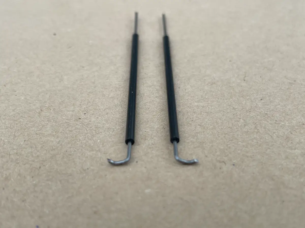
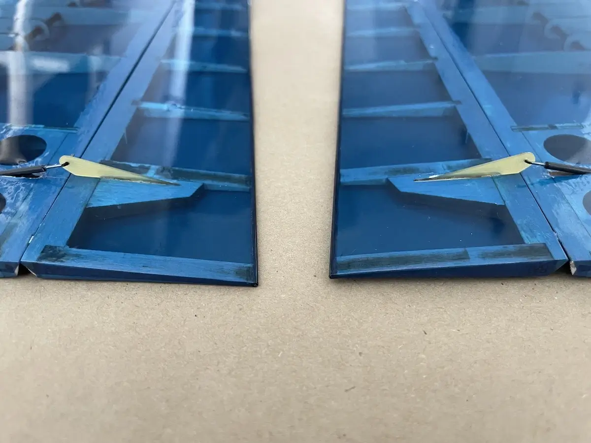
- We recommend using Z-bend on the pushrods inside the wing and L-bend on the control horn side.
- In case you prefer the «open servo horn installation» just cut the openings in the wing servo plates and install the servos sticking the arms through them. Servo clevises might be useful in this case.
- Hinge control surfaces with sticky tape or covering film. We also recommend gluing ~5x10mm mylar hinges spread by ~100mm to prevent control surface play and create a sustainable axis along the edges.
- In case you will notice a slop between the servo arm, pushrod, and control horn, put a drop of CA on the hole while the pushrod is connected. Let the glue cure and move/spin the parts to “break” the glue and make the system move. Now you have a slop-free pushrod connection.
Setup Tricks & Tips
Once done, you are ready to install your receiver, program your transmitter, and head to the flying field.
The SoarOTX F5J template may come in handy here.
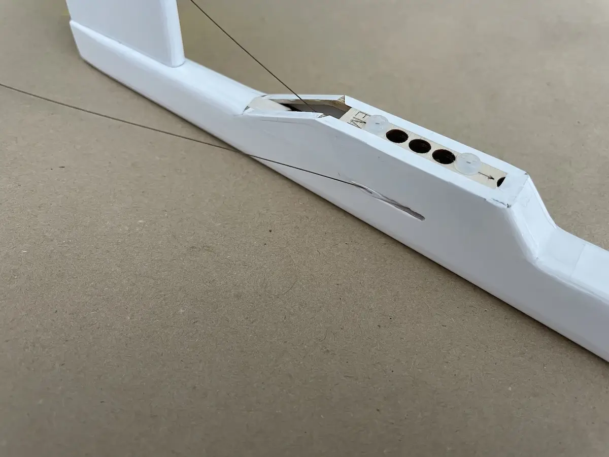
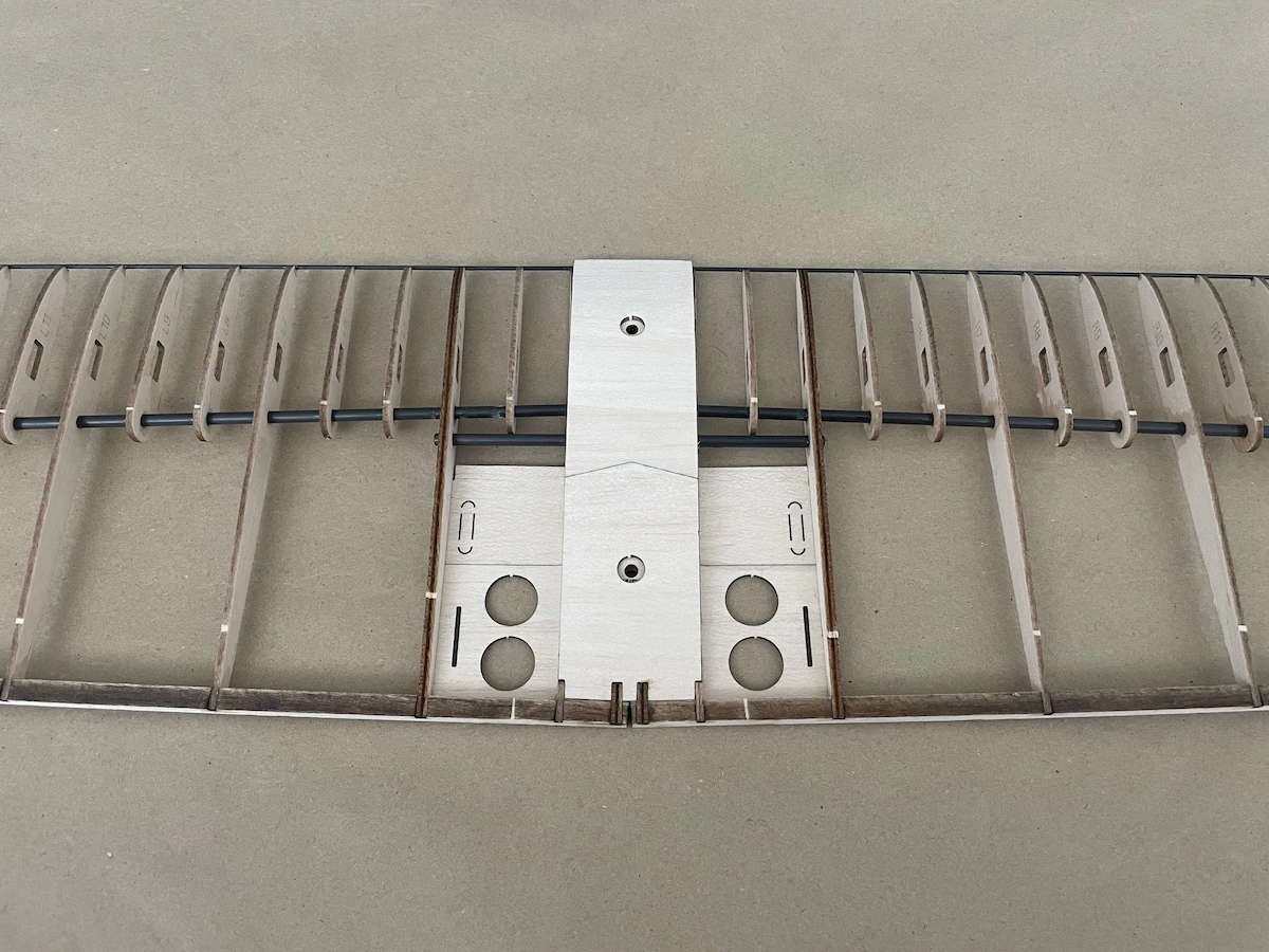
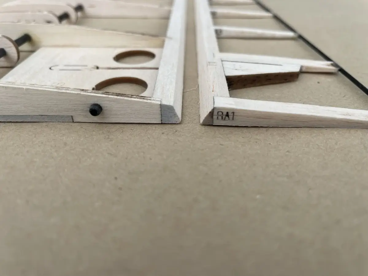
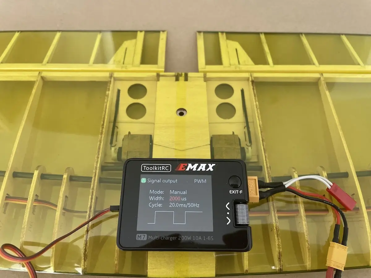
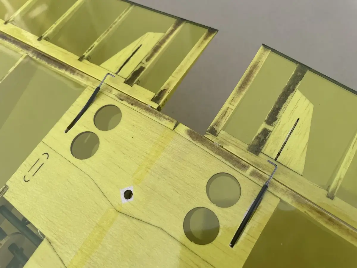
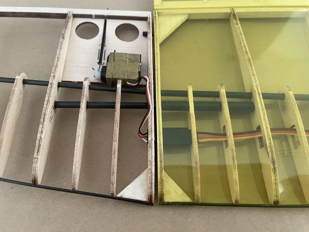
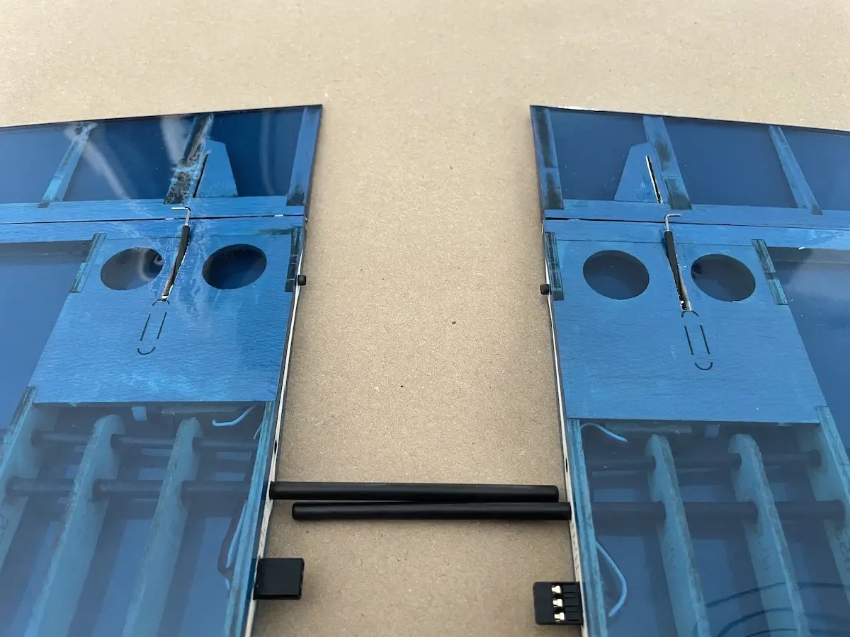
CG Position
For your convenience, we have “marked” a starter Center Of Gravity position on the bottom of the wing sheeting.
These 2 smaller round holes located right under the servos, close to a spar in the picture are the spots where you can put your fingers and check your CG position right at the field.
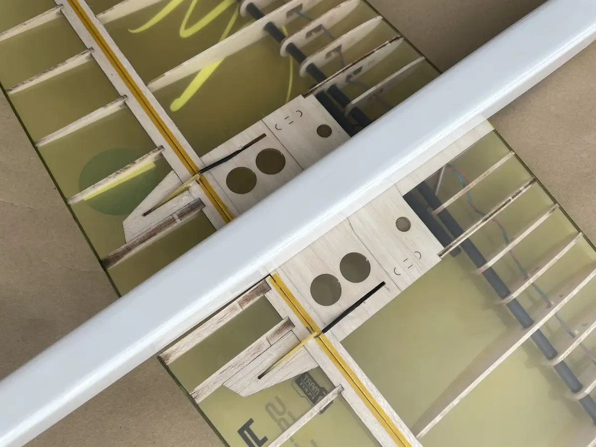
Use it as a starting point, and adjust your CG afterward depending on your preference and flying style.
Please note, that different CG positions will work differently with various camber settings, so there is a wide field for experiments.
Wing Camber Settings
Since the airfoil used for Maverick allows setting up different flight modes, let’s take a closer look at how to set them up.
Usually, there are 4 main camber settings or flight modes which are the following:
- Speed
- Cruise
- Thermal
- Brakes
Speed mode is often used during the launch on the motor, so there is no need to configure a dedicated mode here unless you need it.
Also, the SoarOTX template has all the flight modes pre-programmed, and you just need to set them up. There are detailed video tutorials on this topic.
Note: Camber settings usually apply to both flaps and ailerons. The only exception is the Thermal Mode, where in some occasions you can add more flaps and fewer ailerons if you feel that the glider starts tip-stalling at lower speeds.
| Maverick F5K Control Throws and Camber Settings | |||
|---|---|---|---|
| CG | 85-87 mm from wing leading edge | ||
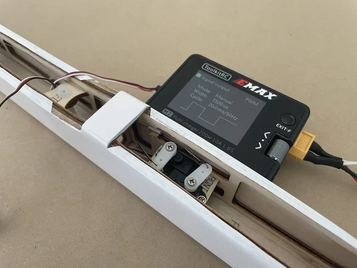
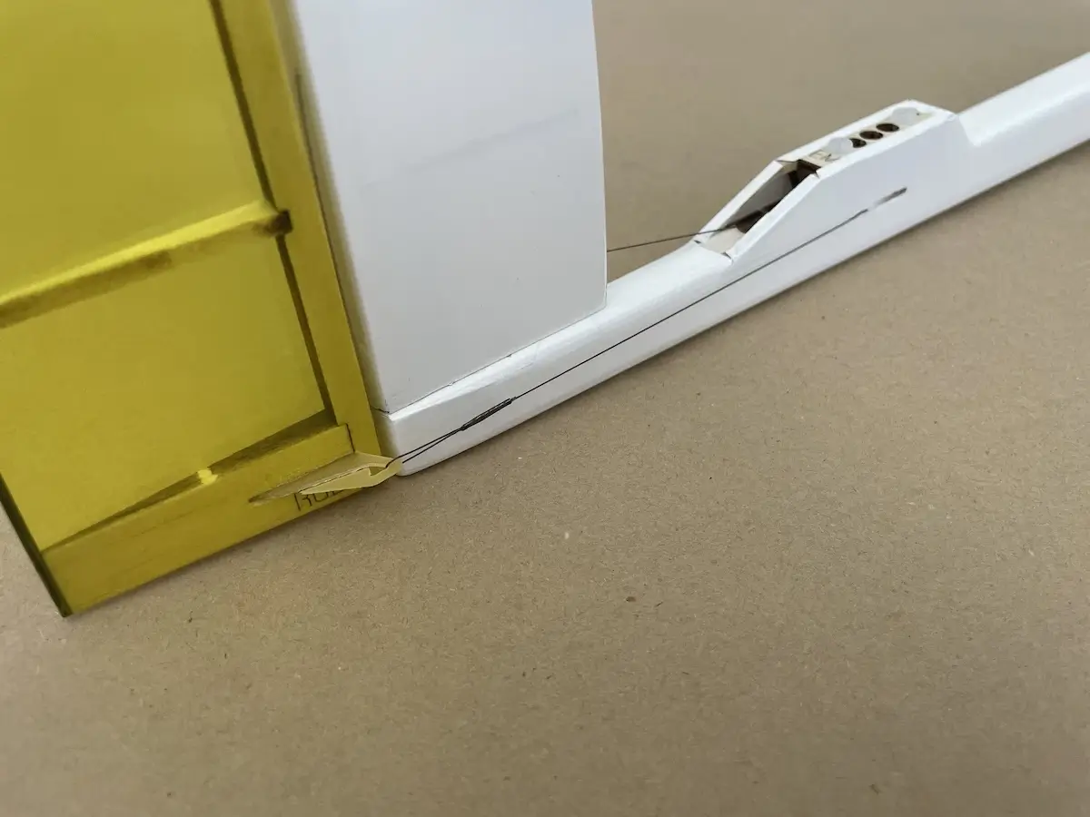
| Rudder | +/- 15mm | ||
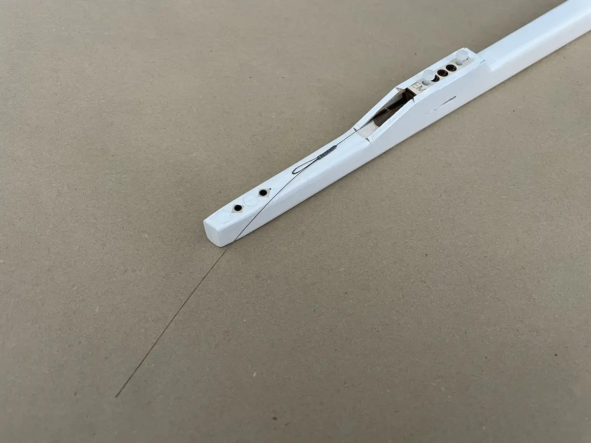
| Elevator | “Touch-the-boom” down, ~13mm up | ||
| Ailerons | 12mm up & 12mm down | ||
| Ail-to-Flap Mix | 6mm up & 6mm down | ||
| Launch & Speed | Flat bottom of the wing airfoil | ||
| Cruise | Flat top of the wing airfoil | ||
| Thermal 1 | 3mm down from Cruise | ||
| Thermal 2 | 5mm down from Cruise | ||
| Brakes (Flaps) | 60°-80°down | ||
| Brakes (Ailerons) | ~45°down/20°up for crow | ||
| Brakes (Elevator) | 5-15°down | ||
Speed Mode
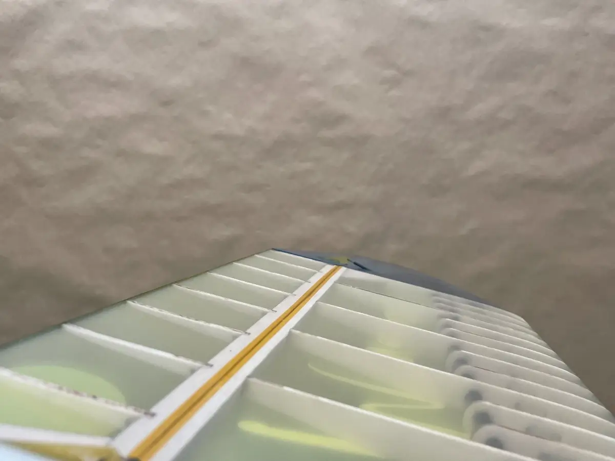
In general, Speed Mode means that the bottom of the wing is completely flat. Use a ruler as a reference or check this video to learn about a “reflection method”.
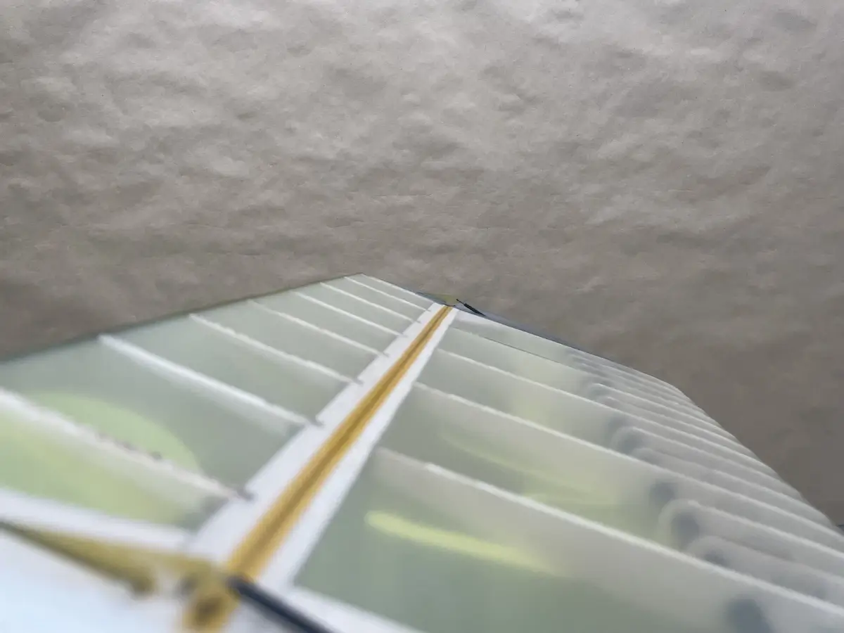
Cruise Mode
In Cruise Mode, make the top surface of the wing flush with the flap and ailerons, making for a smooth line. This will add some angle to the bottom increasing efficiency of the wing with a little drag and as a result speed penalty.
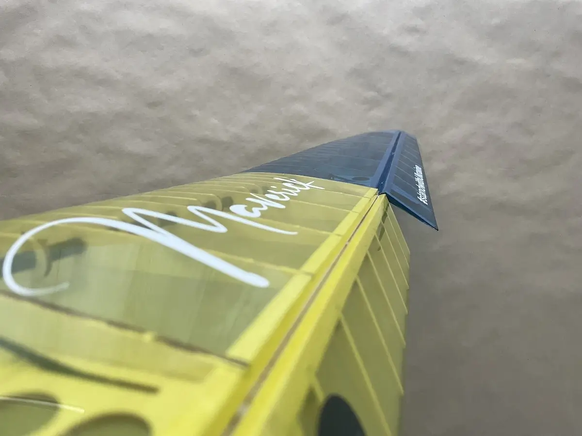
Thermal Mode
For Thermal Mode, set your flaps 3-5mm lower than in Cruise Mode, measured on the fuse. We don’t recommend moving lower than this as the glider stops flying then. But you are free to experiment.
Then, align the ailerons with flaps to have a consistent airfoil throughout the whole wing span, or adjust them to a slightly smaller angle to have more roll control and a more stable wing.

Brakes
There are various options that you can use for braking to slow down your glider.
Some of them are:
- Crow Brakes – Ailerons Up, Flaps Down
- Flaps only – when the Ailerons stay untouched
- All down – Ailerons and Flaps move down simultaneously
All methods usually require some down compensation settings on the elevator, as the glider usually starts ballooning up as soon as you apply brakes.
This is one of the reasons why pilots usually prefer to control brake application with a throttle stick. It provides easy and adjustable control depending on the flight conditions.
Our preference is the third option, when all wing control surfaces move down, while Ailerons travel around 1/2 of the distance that Flaps do.
This helps to keep the glider “flying” but at a drastically reduced speed and stay controllable for a precise hand catch.
One last thing, all the above are our recommendations and you are free to experiment and develop the settings that work the best for you.
Get Ready For Maiden!
Choose the right weather and head to the flying fields.
Take your RC mates with you in case you need help or just company to cheer you on your first flight with a new glider 😉
Note, we do not recommend flying Maverick in winds over 8m/s (or 15 knots). Considering that a build-up construction is less rigged compared to the composite models, you can do this at your own risk.
For some inspiration, take a look at this beautiful flight video by BavarianRC
And please, share your build and flight report in the Maverick thread on RCGroups.
Happy flying!