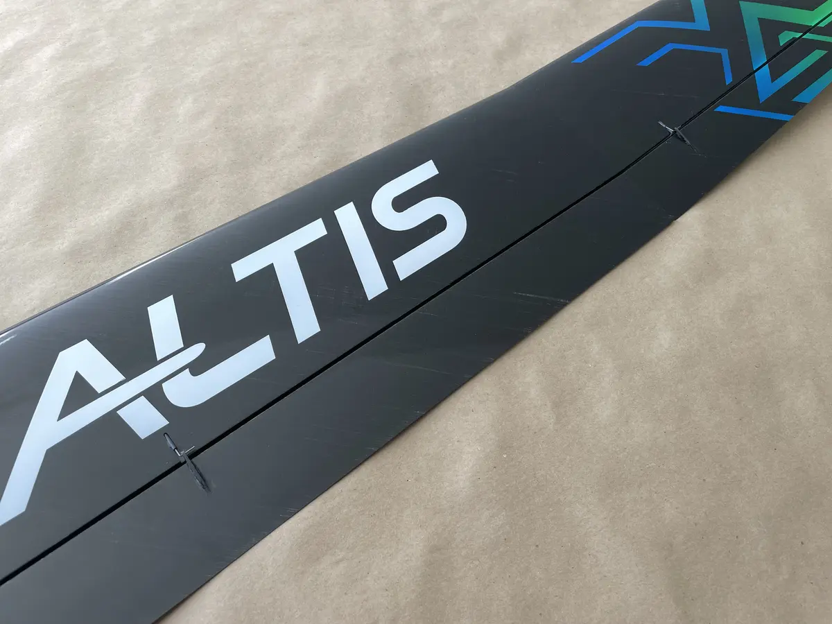
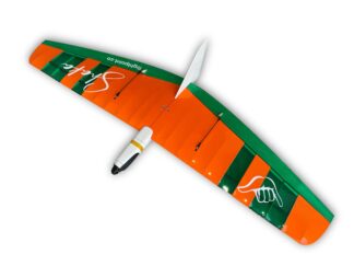
Altis F5J-400 is the next model by K. A. Composites – the manufacturer of the Sabre F5K.
It is a 2.5-meter model that features:
A full-house carbon wing
Rocacel cores on the wings and tails – (CA-friendly)
2-section main wing, and a single-piece fuselage
Pull-spring linkages for tail feathers
A complete accessories pack
…and can be assembled with a wide selection of components, depending on your liking.
So, please, treat this guide as your reference, and choose your way of building and selecting components accordingly.
Btw, if you wish to share your build process, or learn from the other pilots, please check this RCGroups thread on Altis F5J-400.
Before You Start
Starting the Altis F5J-400 build is fairly simple.
The airframe comes 95% ready, and your only job is to complete it like a LEGO… kind of…
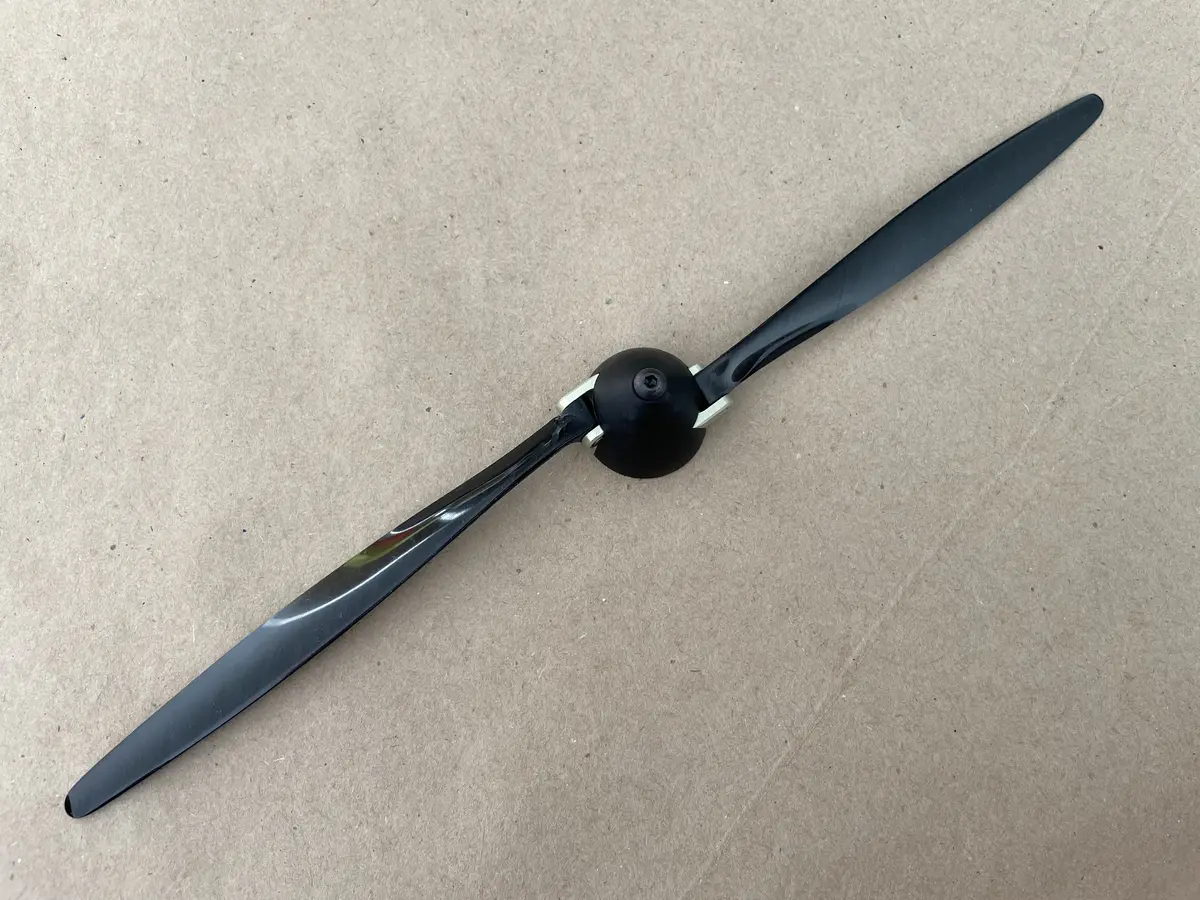
Check for RC gear recommendations on the product page in order to select the right servos, motor, prop, and spinner.
Then, make sure to prepare some tools and supplies required for the build:
A sharp model (or paper) knife
Medium CA with kicker or epoxy resin if you prefer
Masking tape
Diamond files
Tweezers
Pliers
Flathead and Phillips-head screwdrivers
Sandpaper
Kapton tape, or the other sticky tape that you prefer
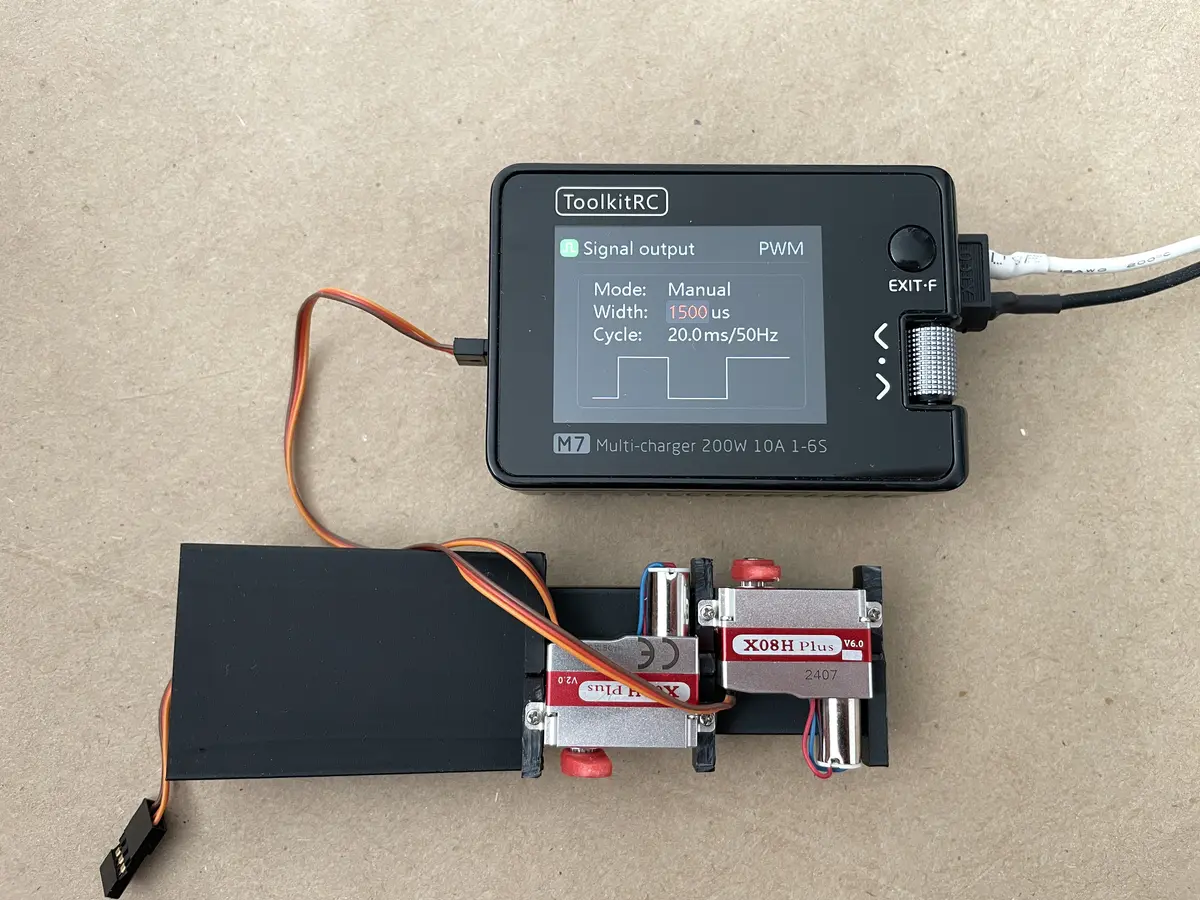
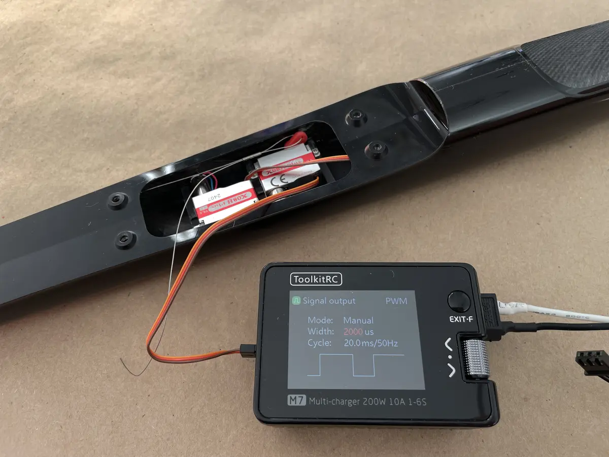
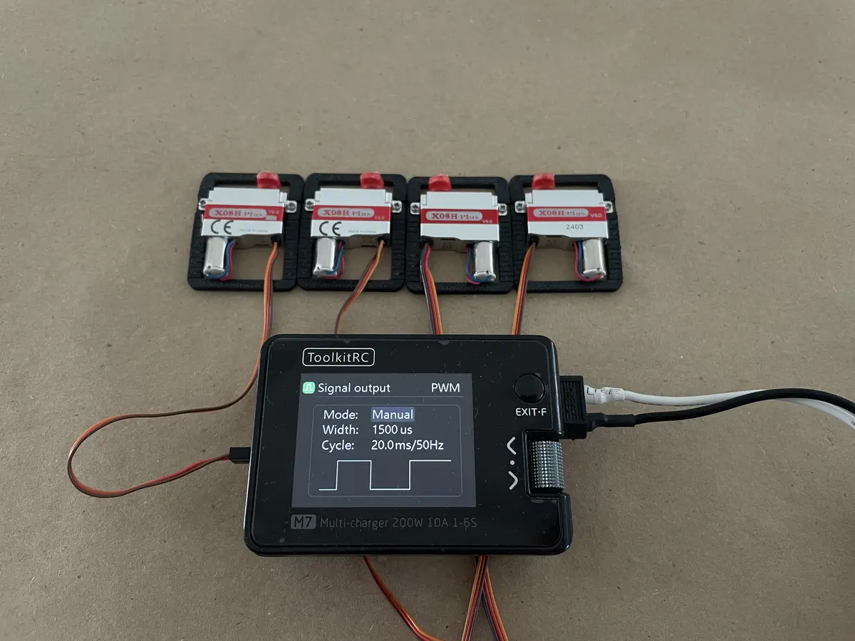
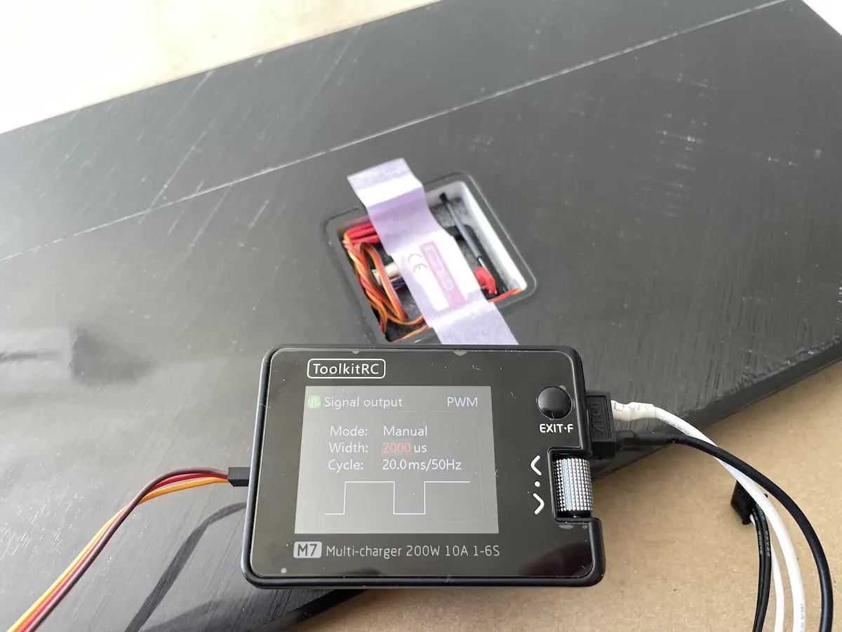
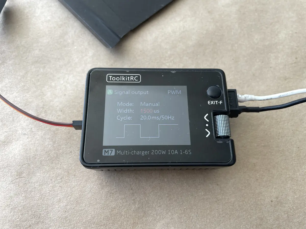
A servo tester, or just your Rx
A tiny 1-1.5mm drill bit.
Once ready, you can jump right on.
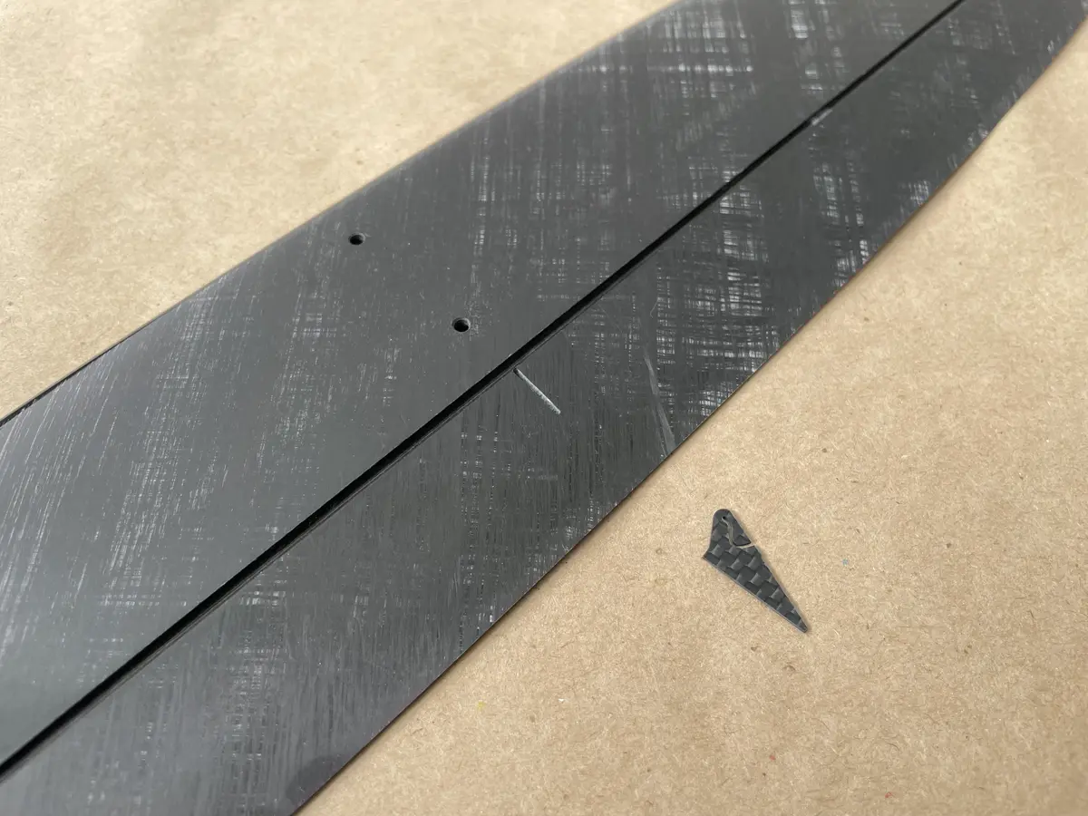
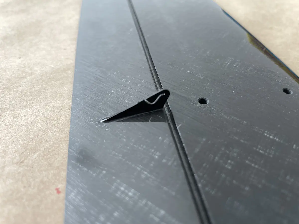
Part 1. The Tails
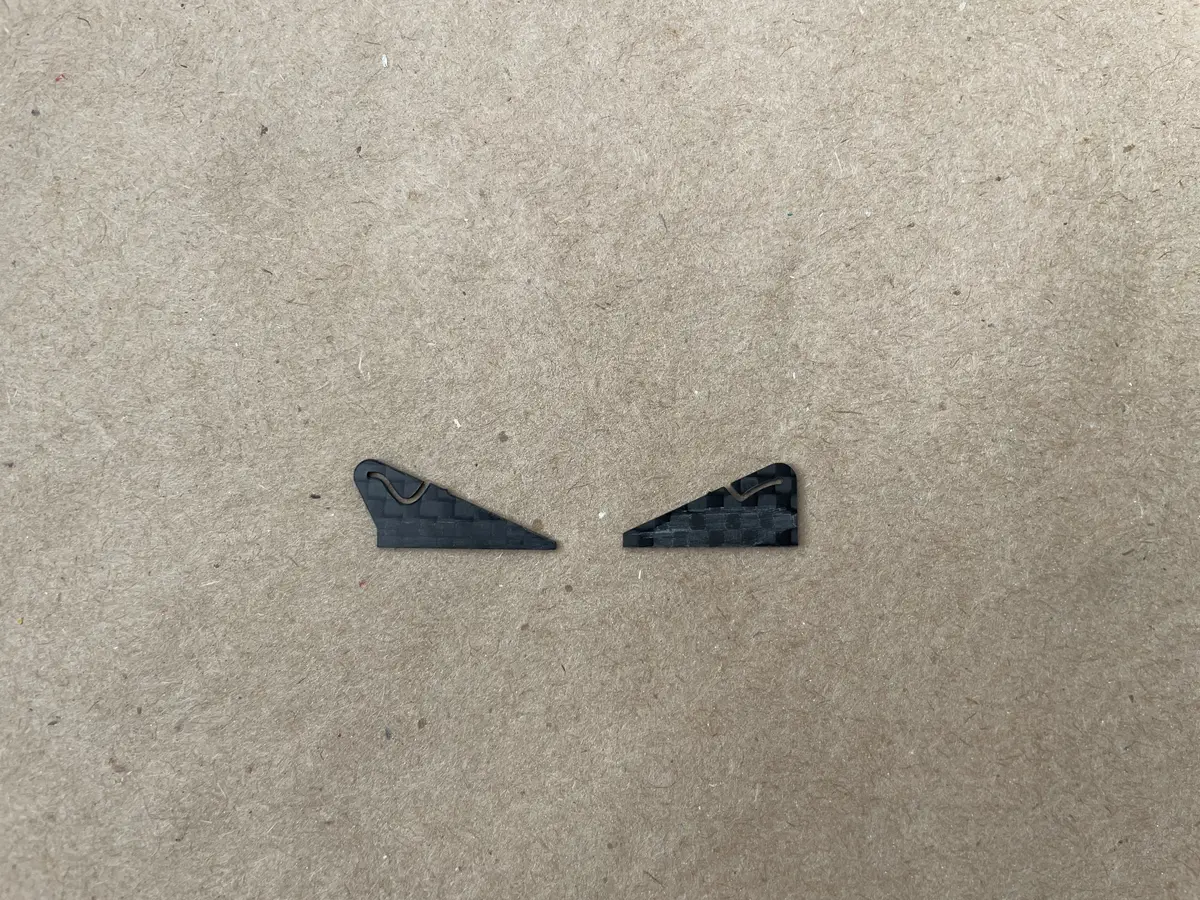
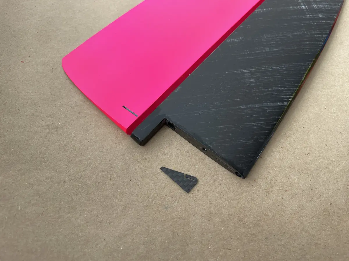
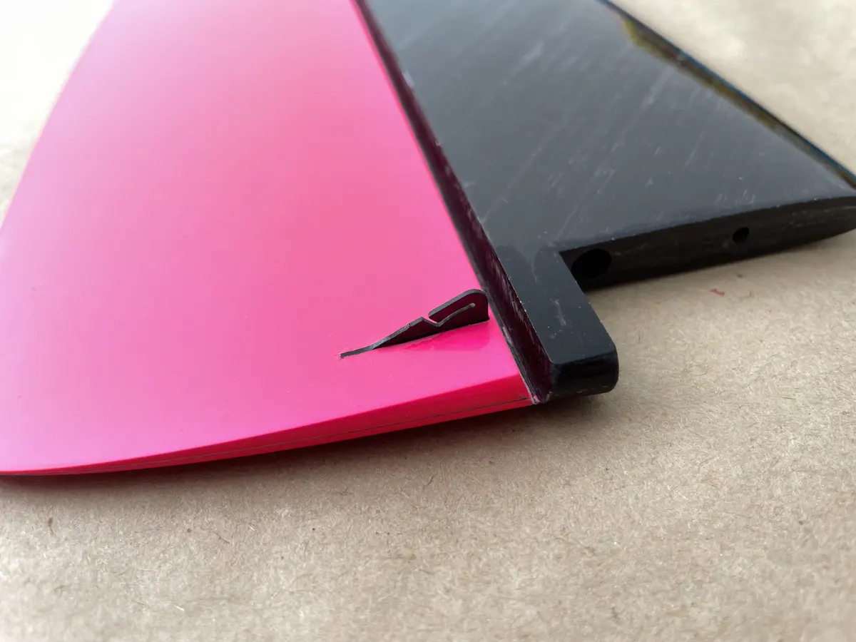
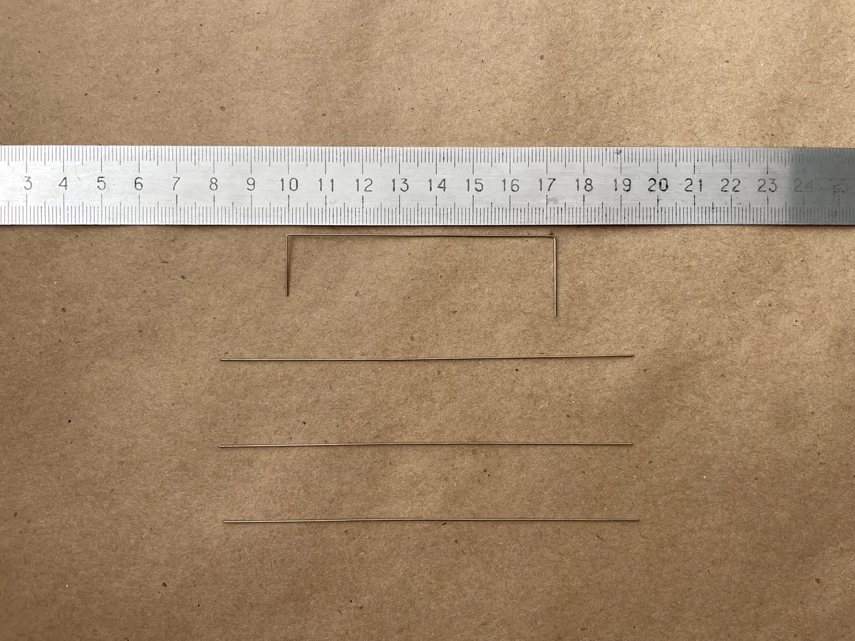
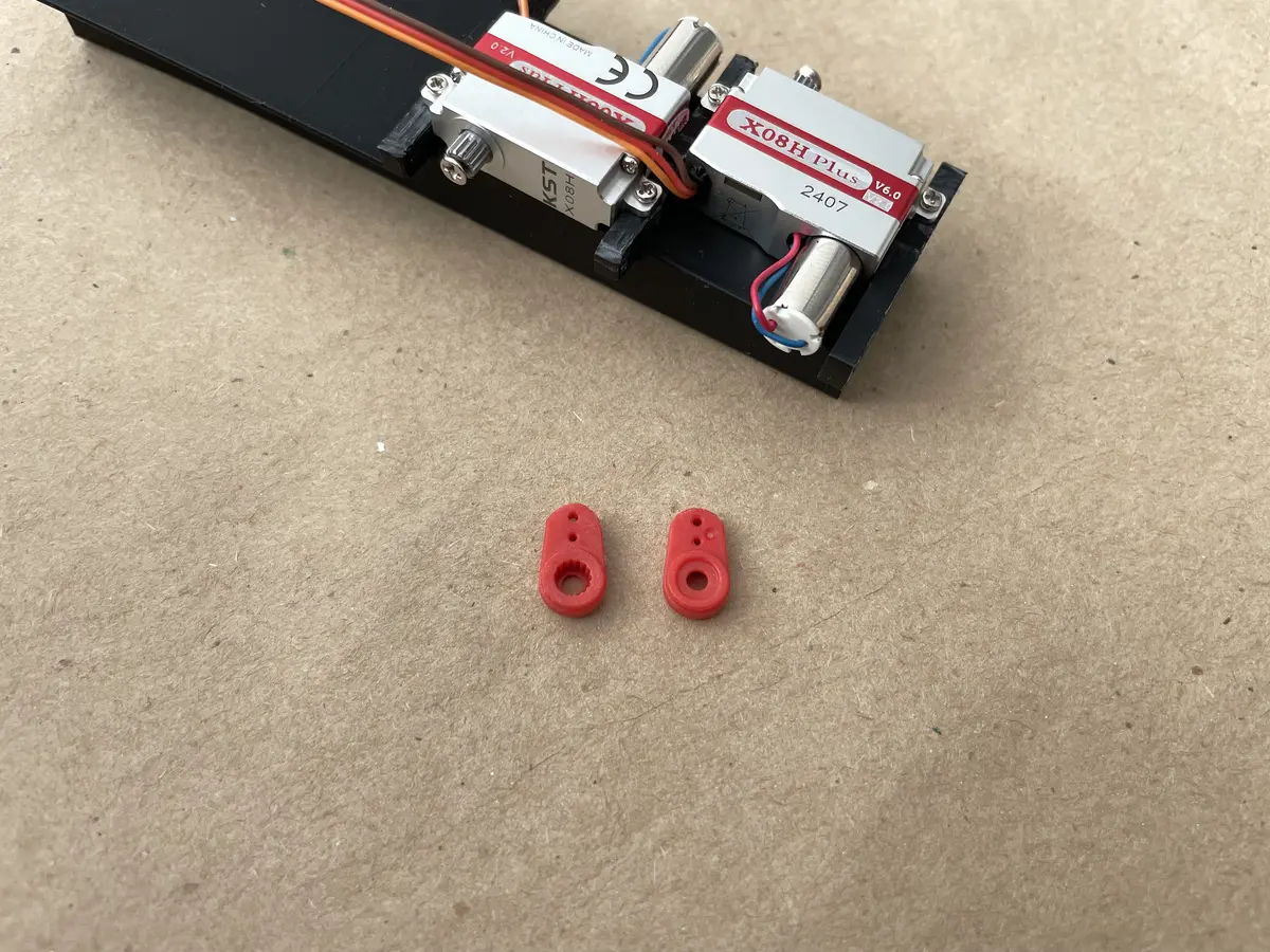
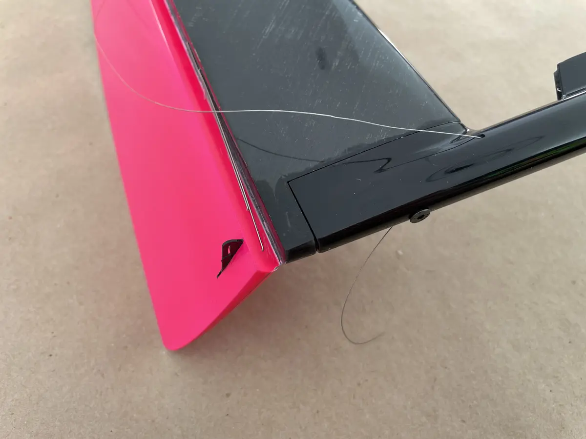
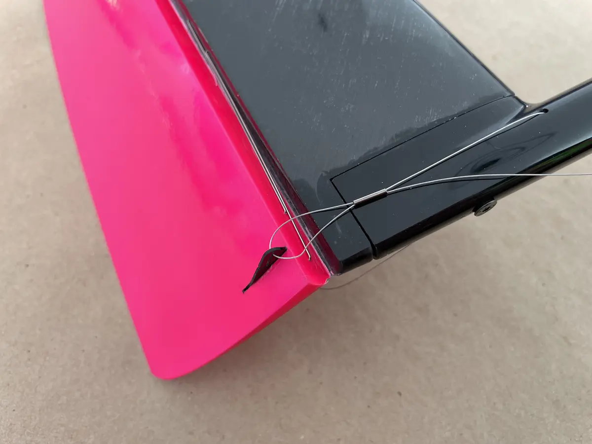
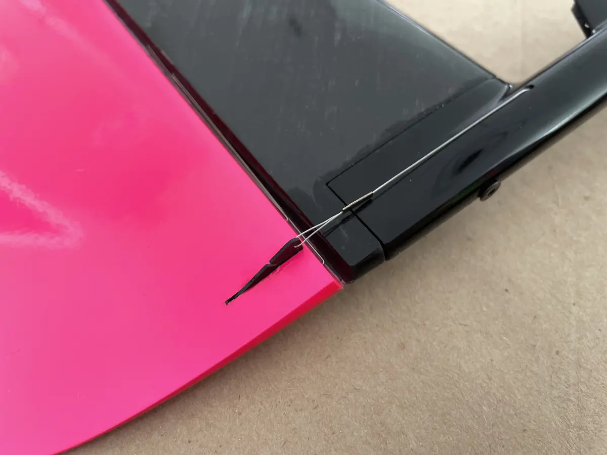
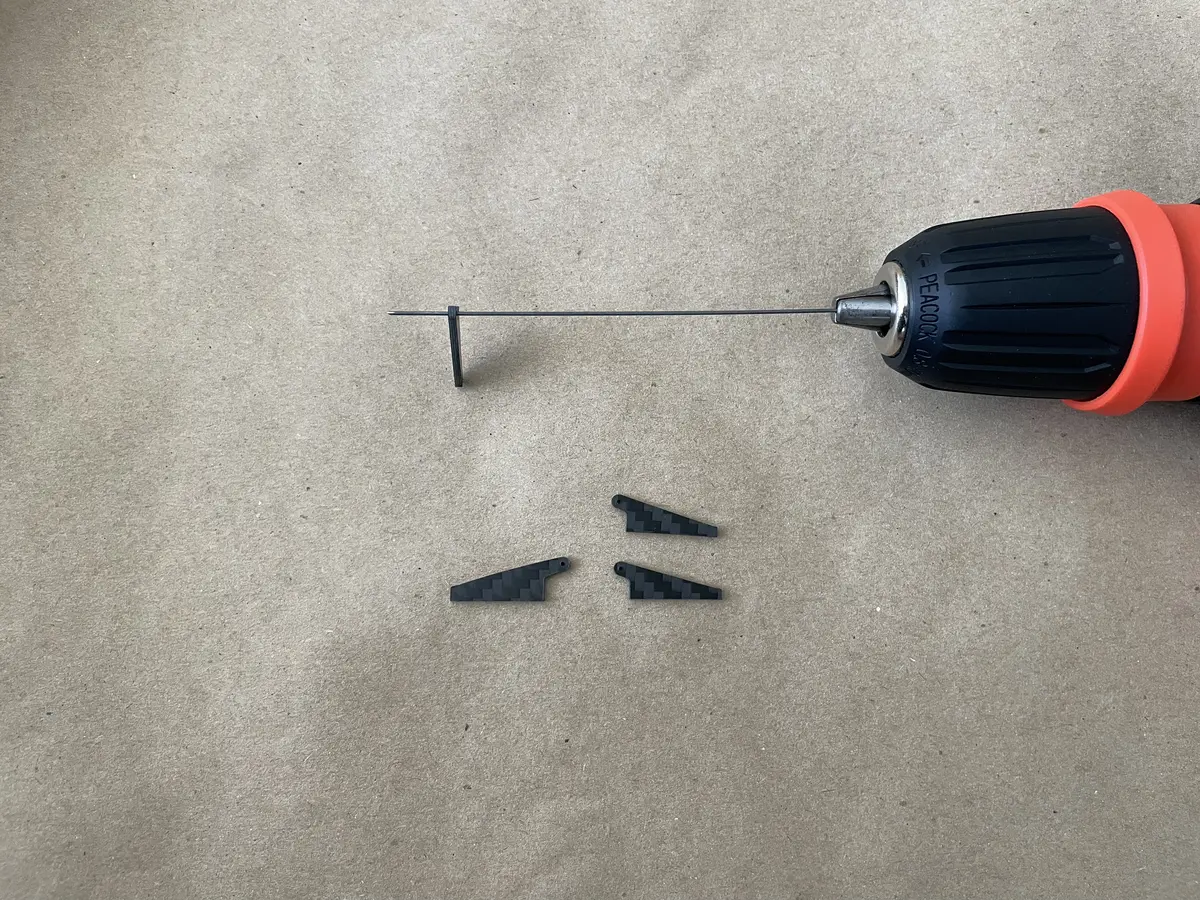
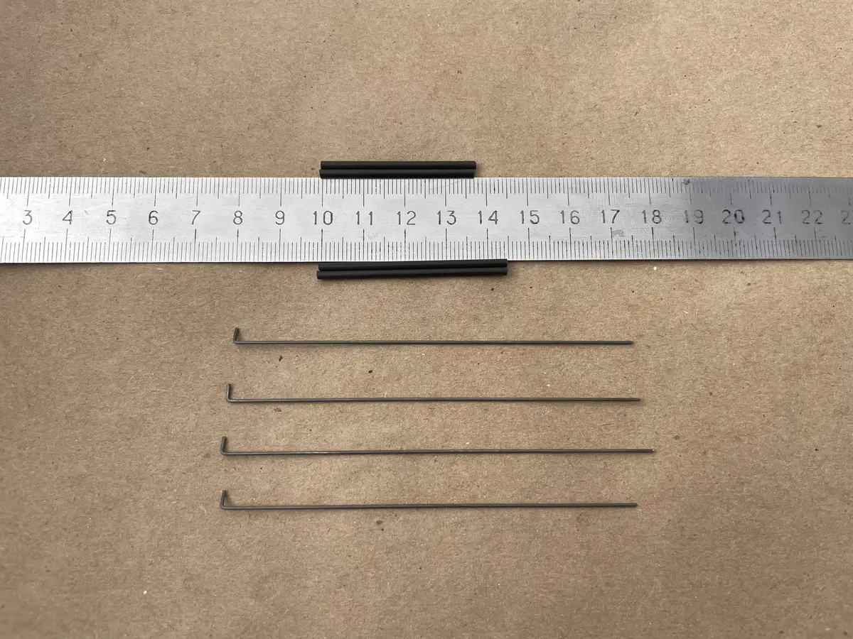
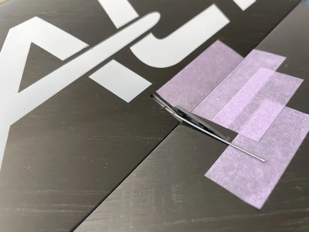
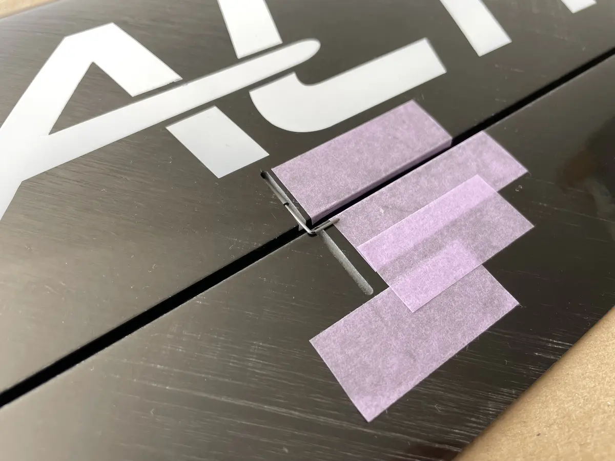
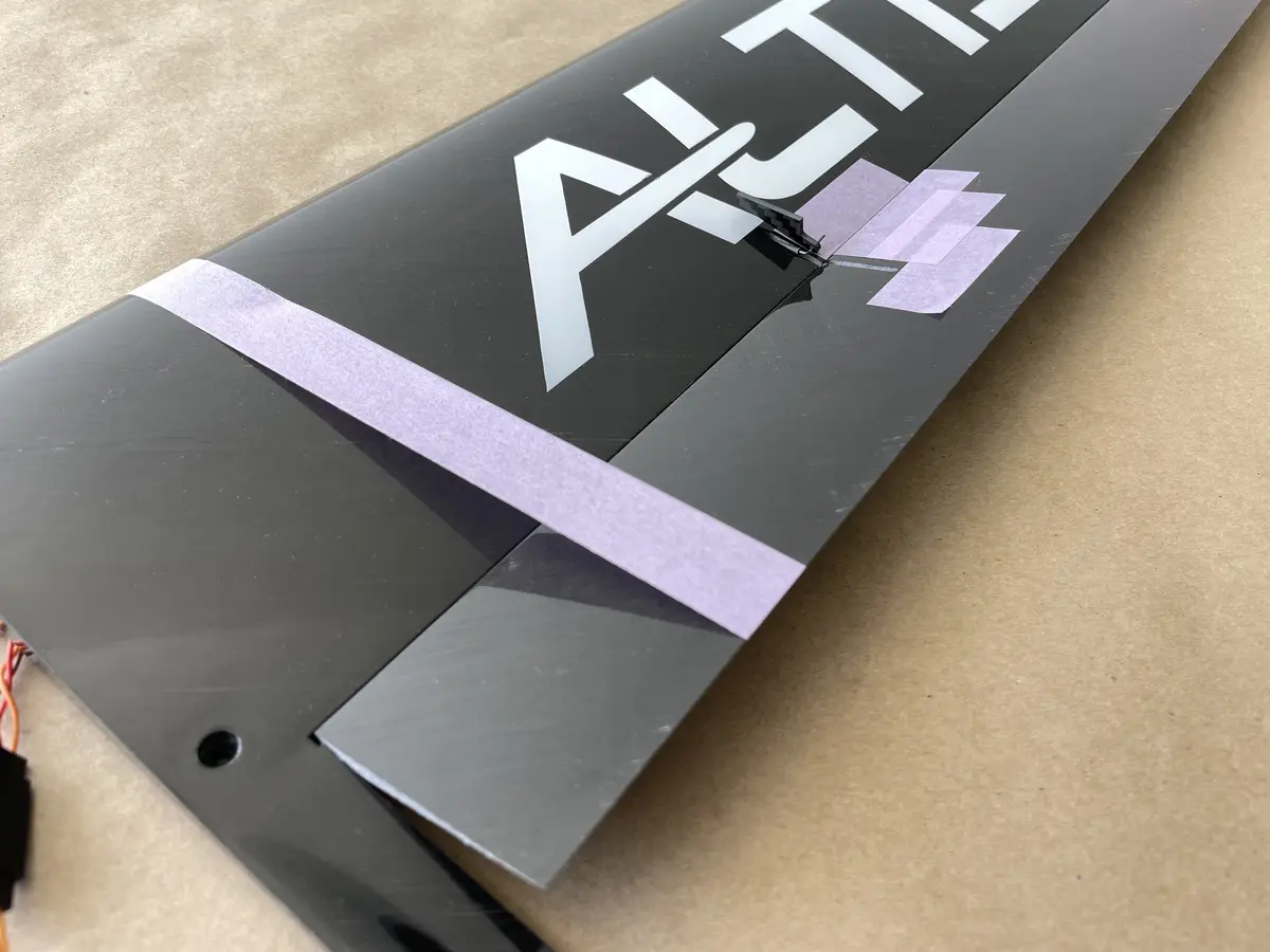
Identify the correct control horns – left is for the Elevator, right is for the RudderDry-fit the control horn into the slot in the Rudder. Adjust as neededPosition the elements and apply medium CA to fix it permanently.Repeat the same process for the Elevator hornApply a fair amount of CA or Epoxy to create a healthy fillet on both sides of the control hornBend the supplied music wire into C-shapes to create torsions. You’ll need two for each control surfaceIncert a shorter leg of your torsion into the Rudder near the control horn, and the longer one into the fin. Repeat the same for the Elevator – Stab, but this time position the torsions on both sides of the control horn.
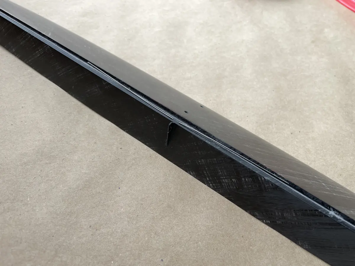
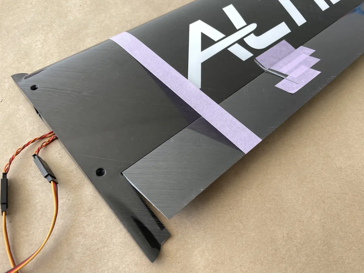
Part 2. Fuselage
The fuselage assembly is not that hard either.
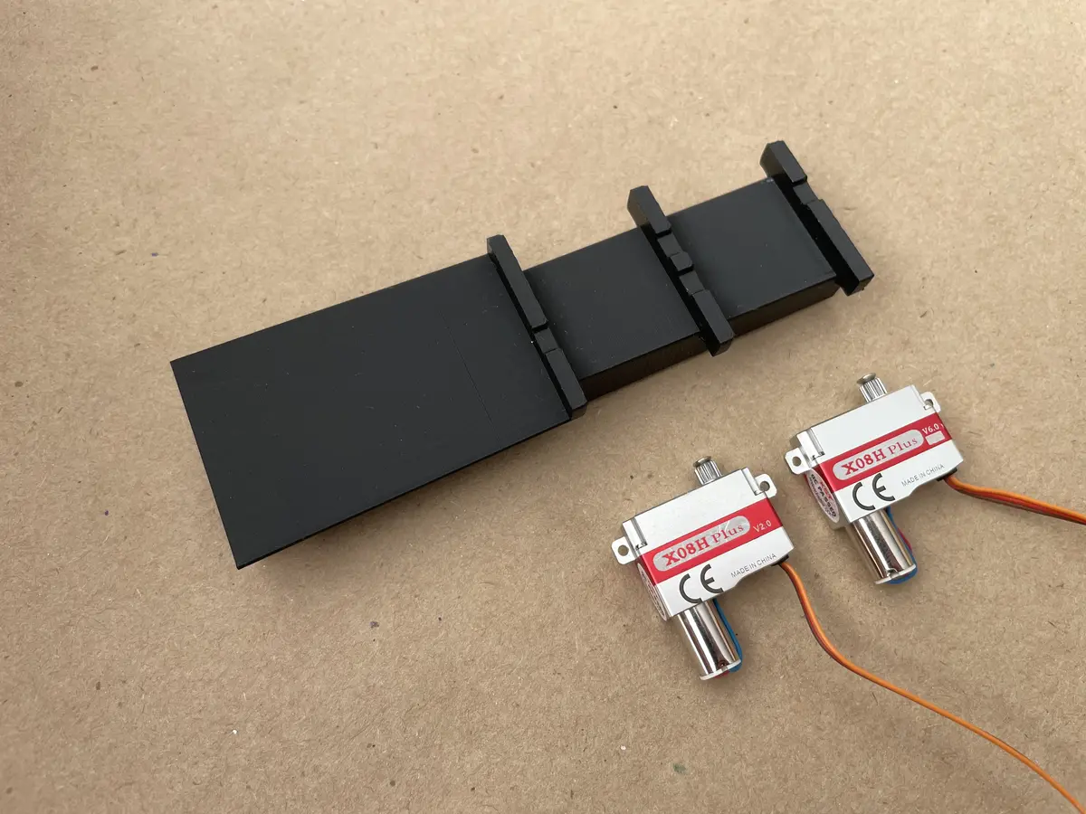
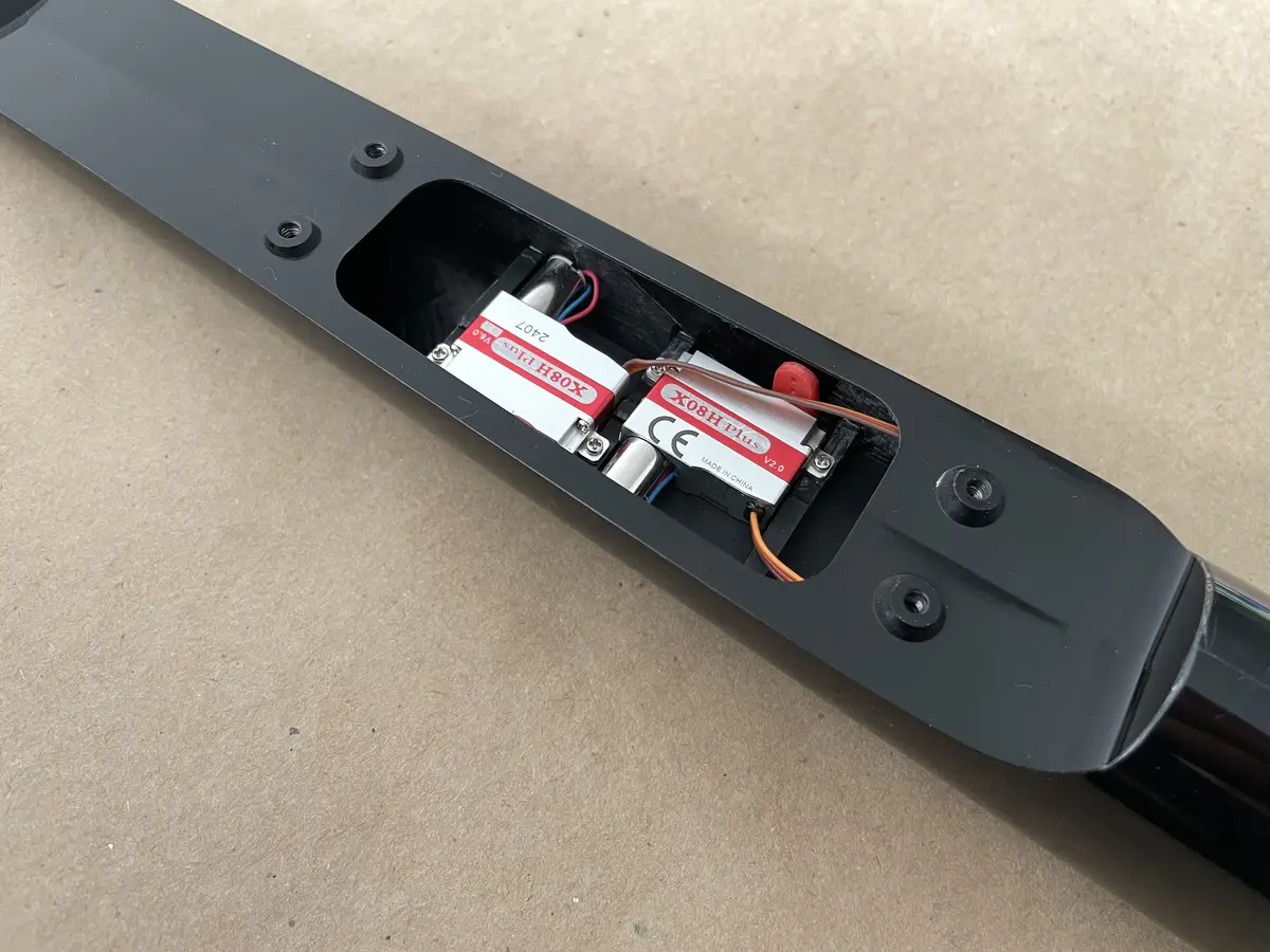
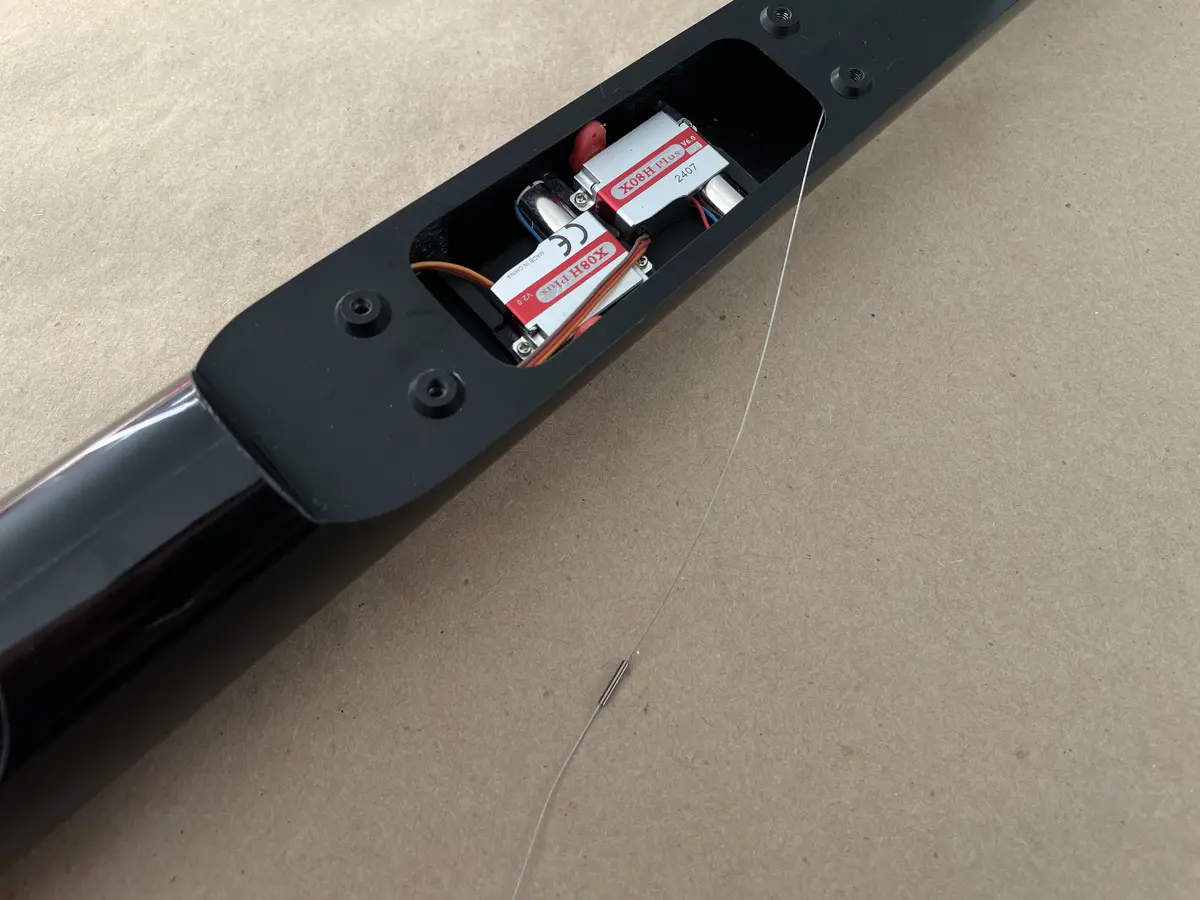
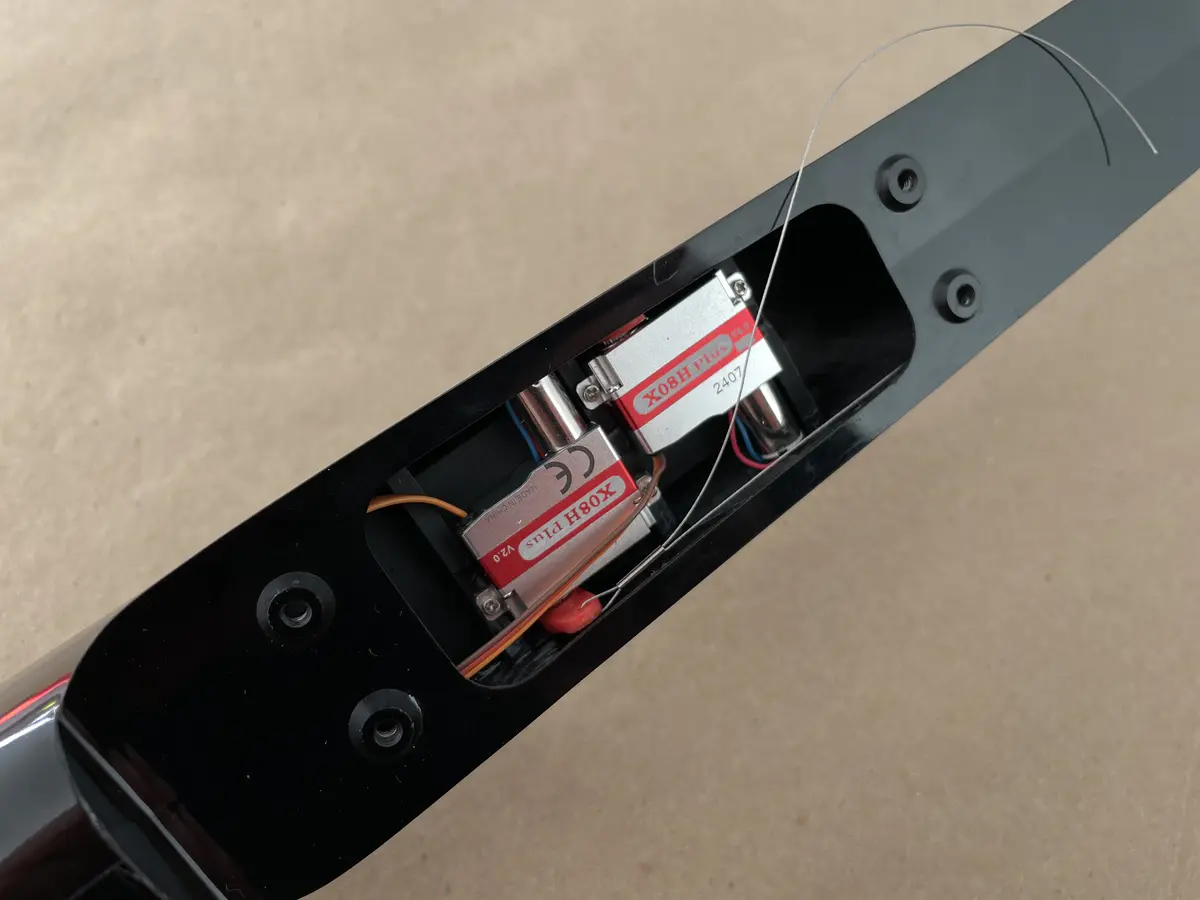
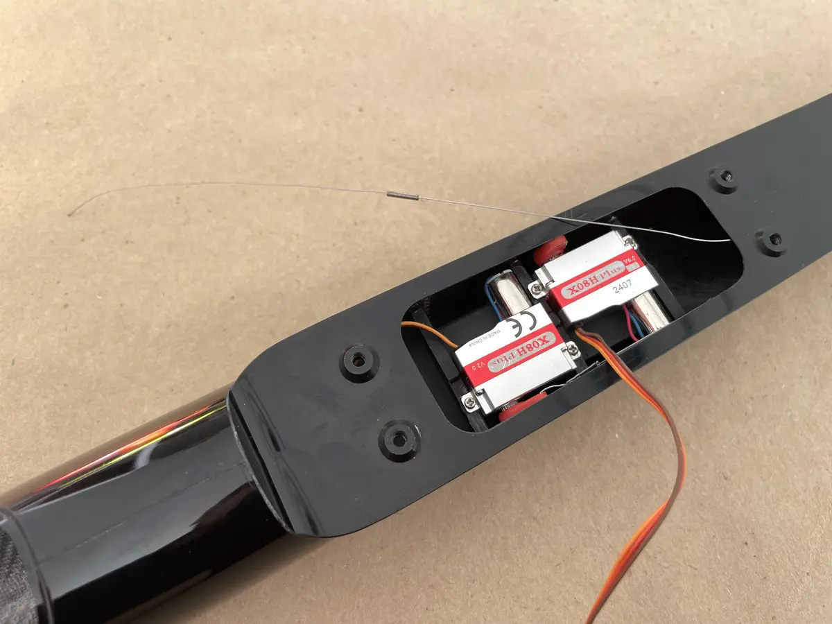
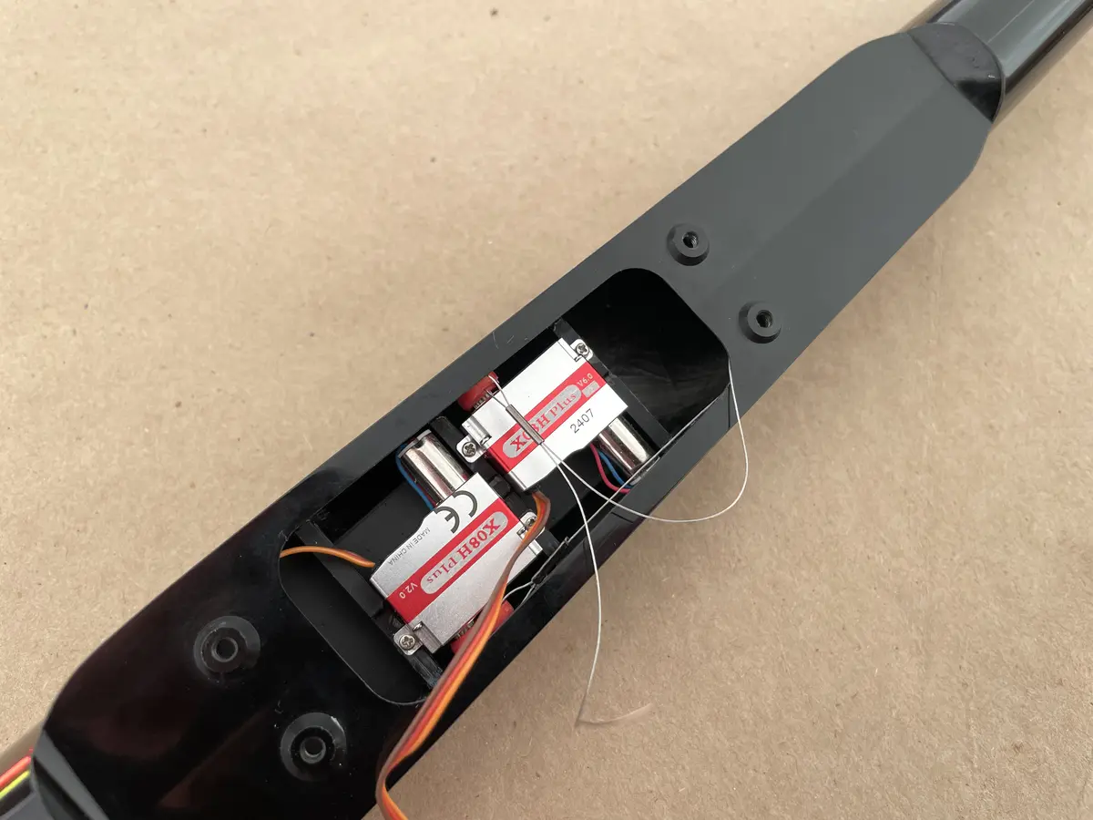
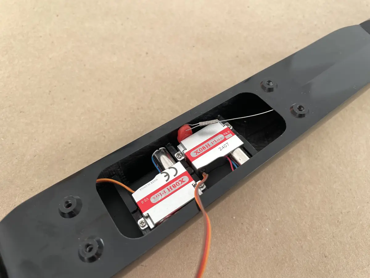
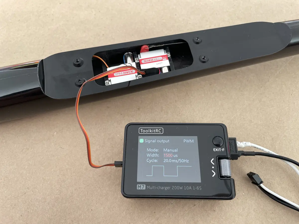
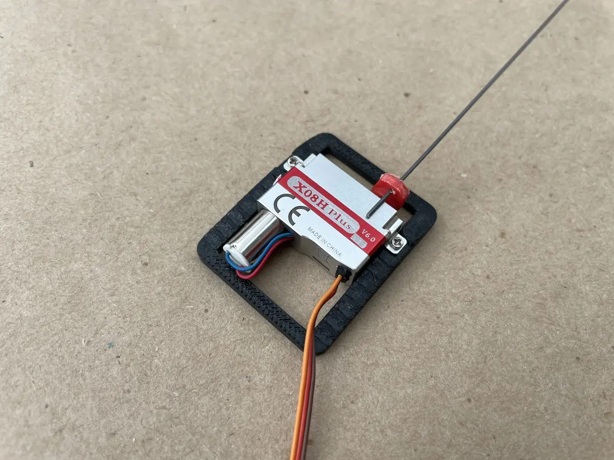
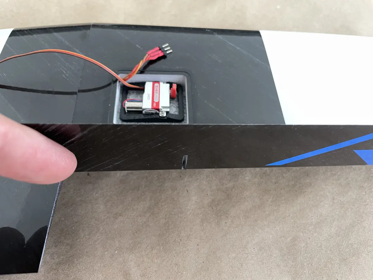
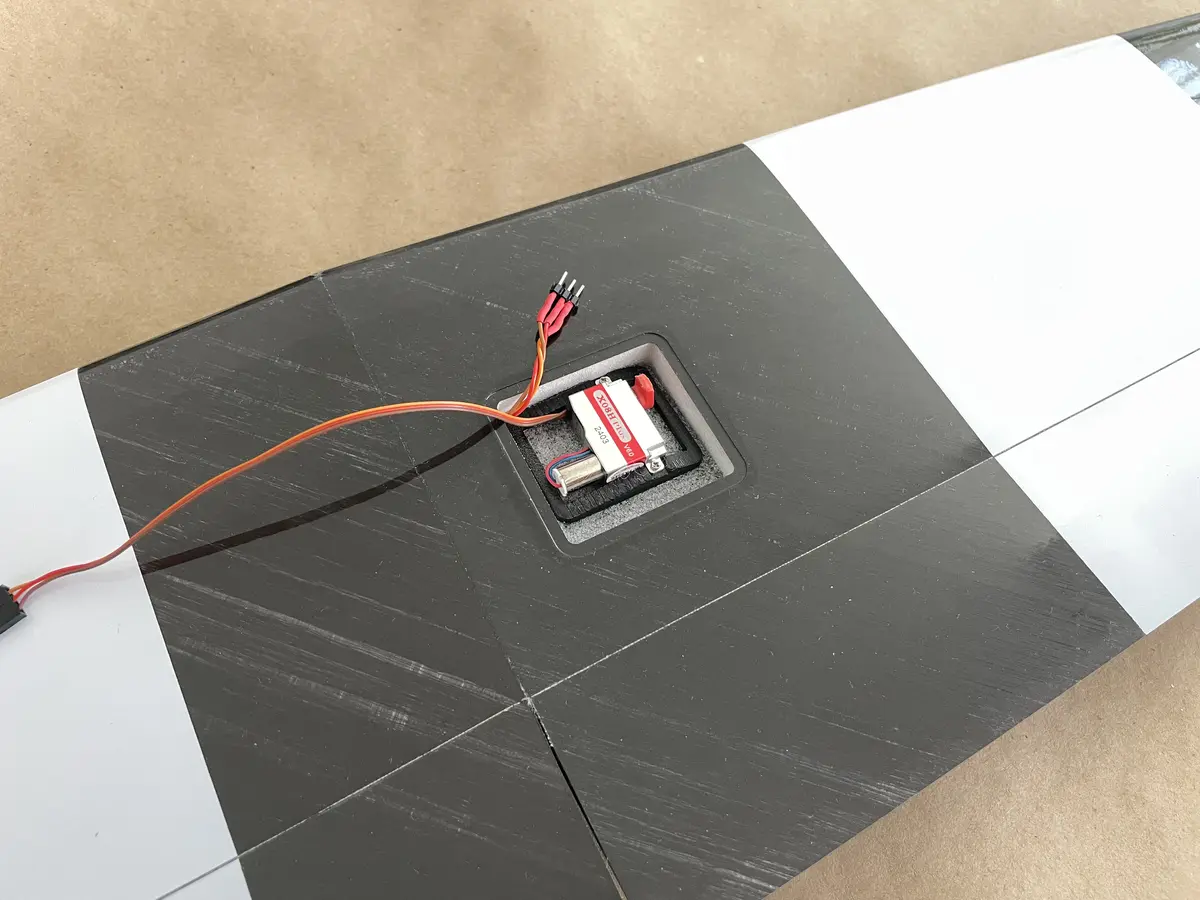
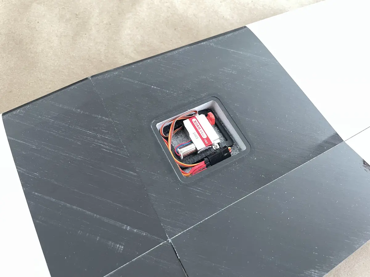
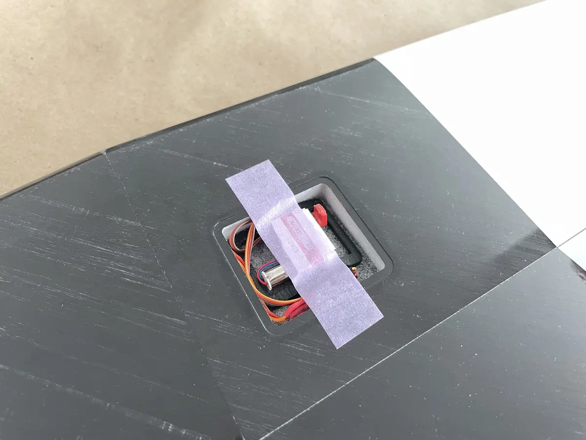
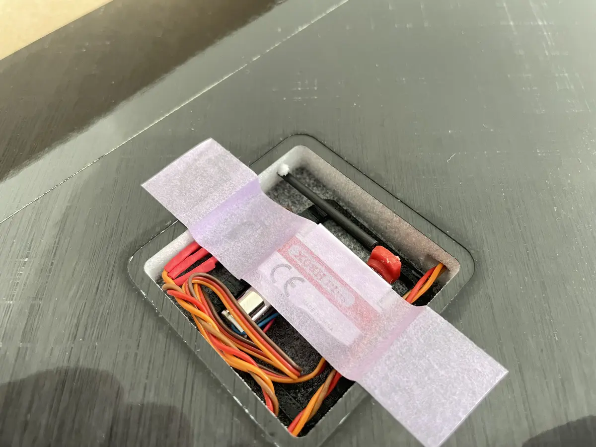
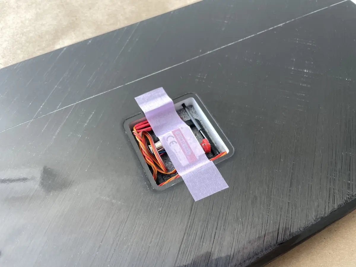
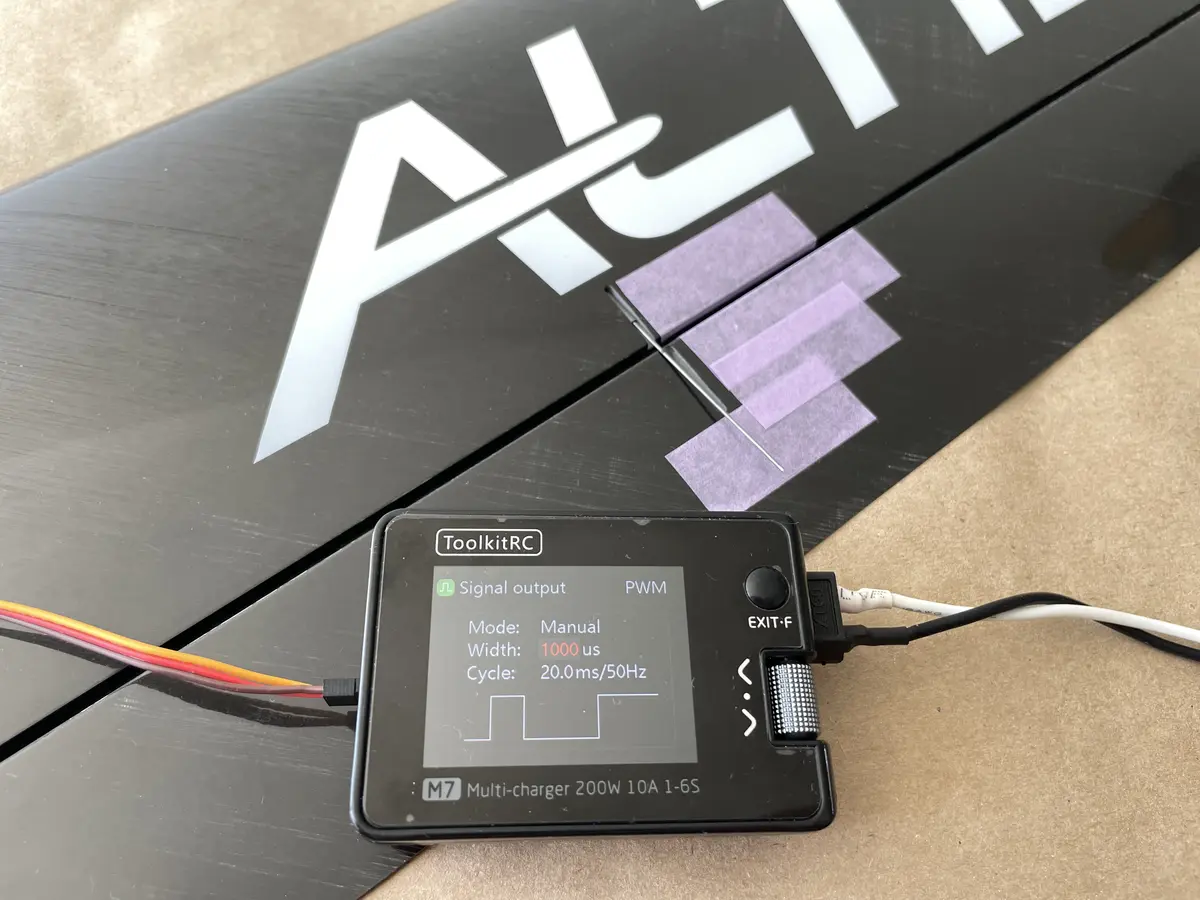
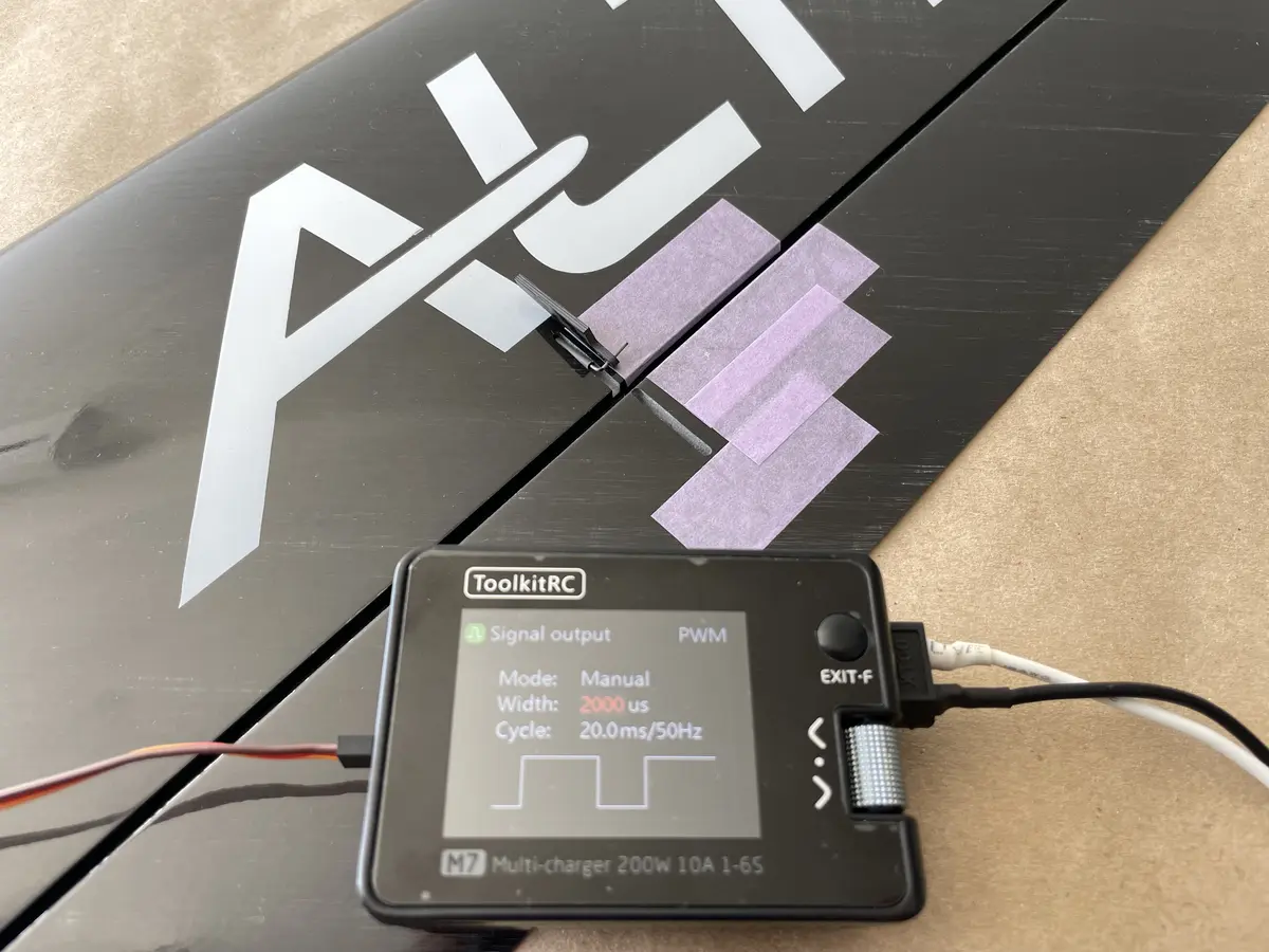
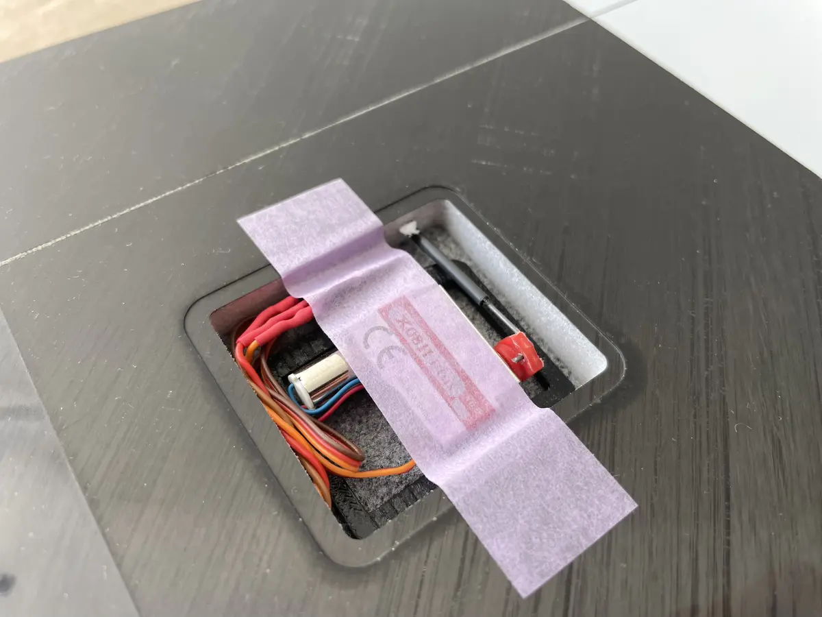
Prepare two flat-mounted servos, KST A08 works best, and a servo tester (or your radio) to play wiht the servos during the process.
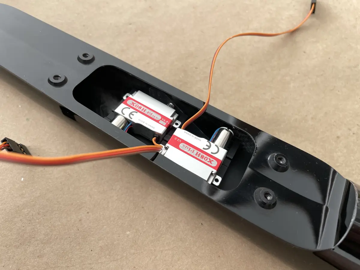
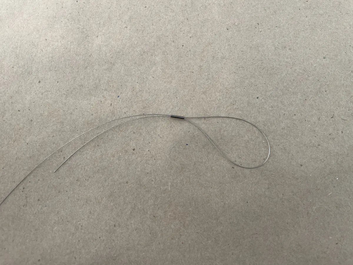
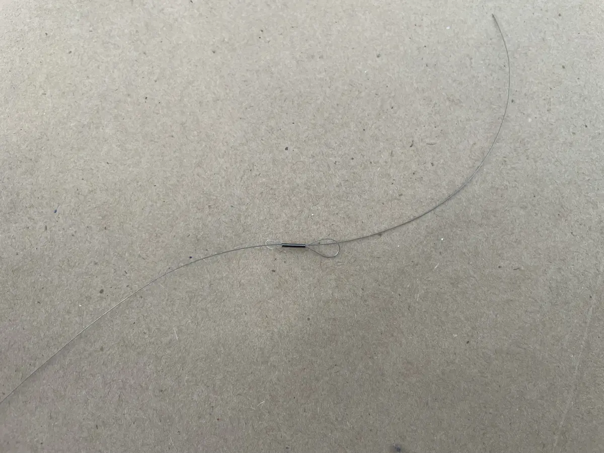
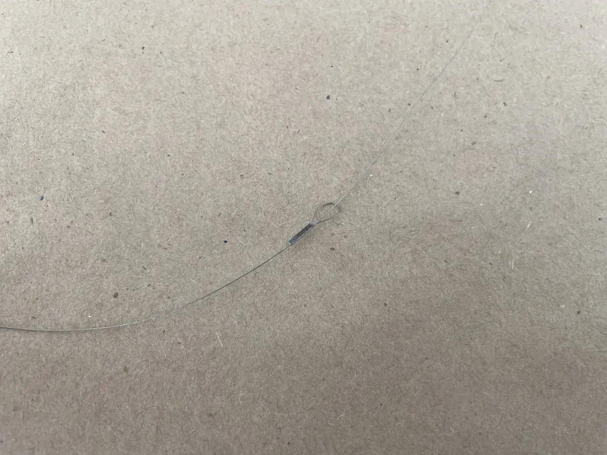
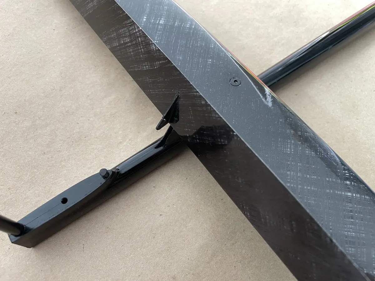
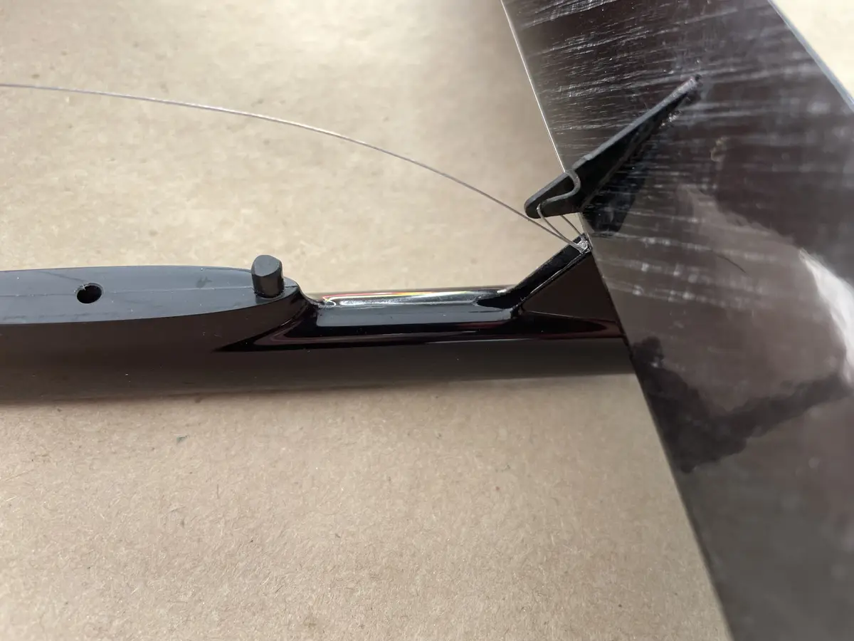
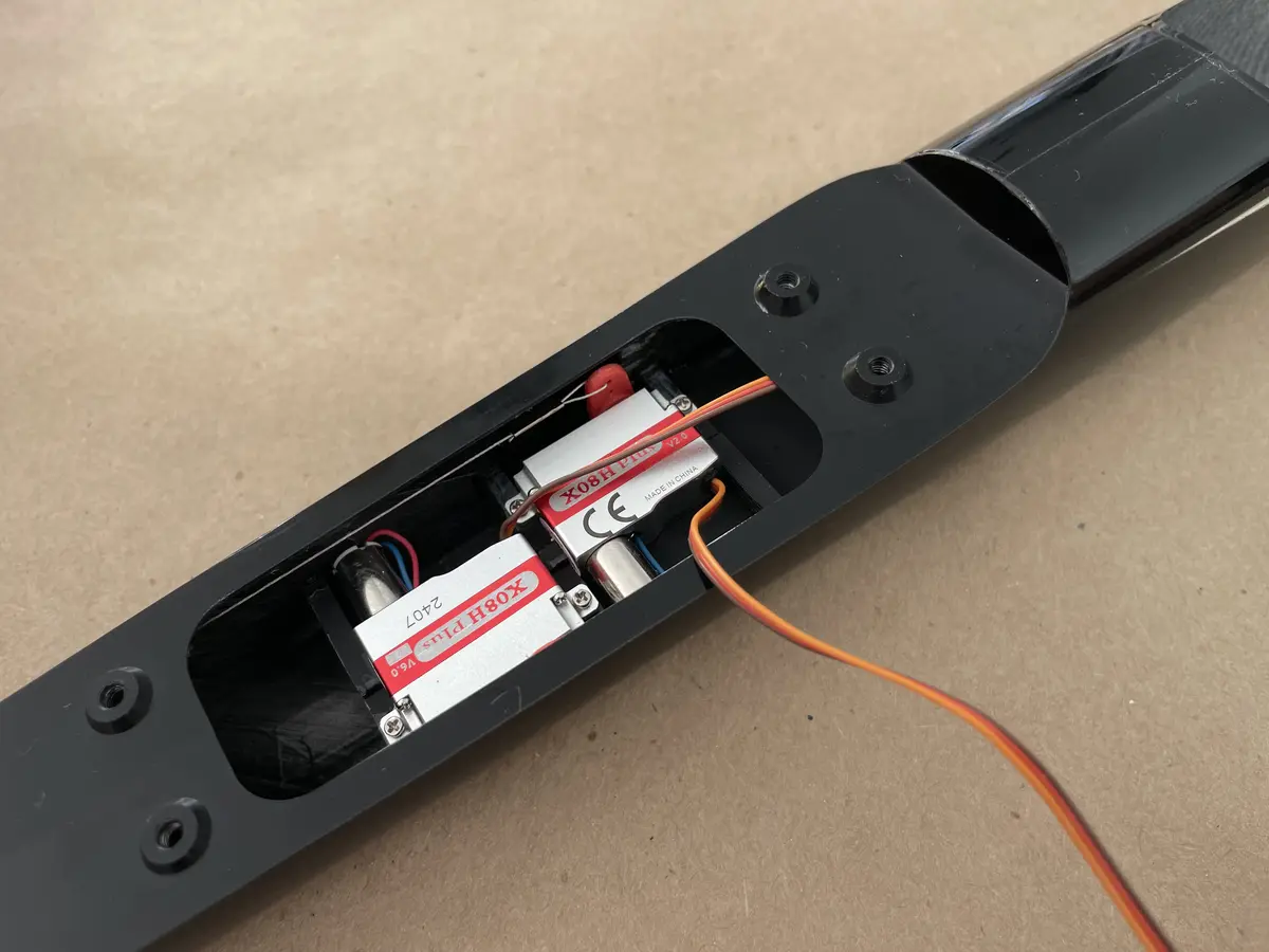
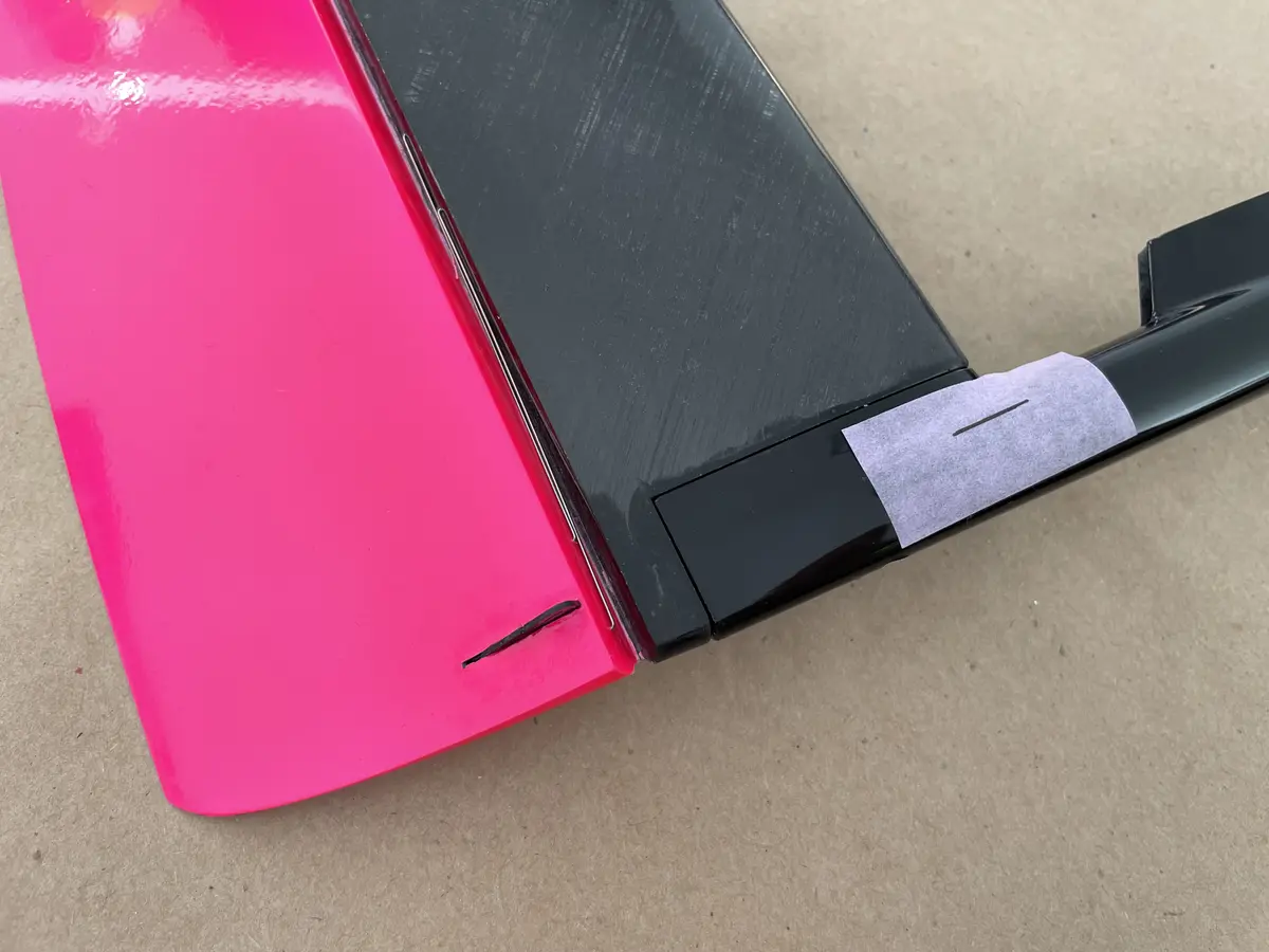
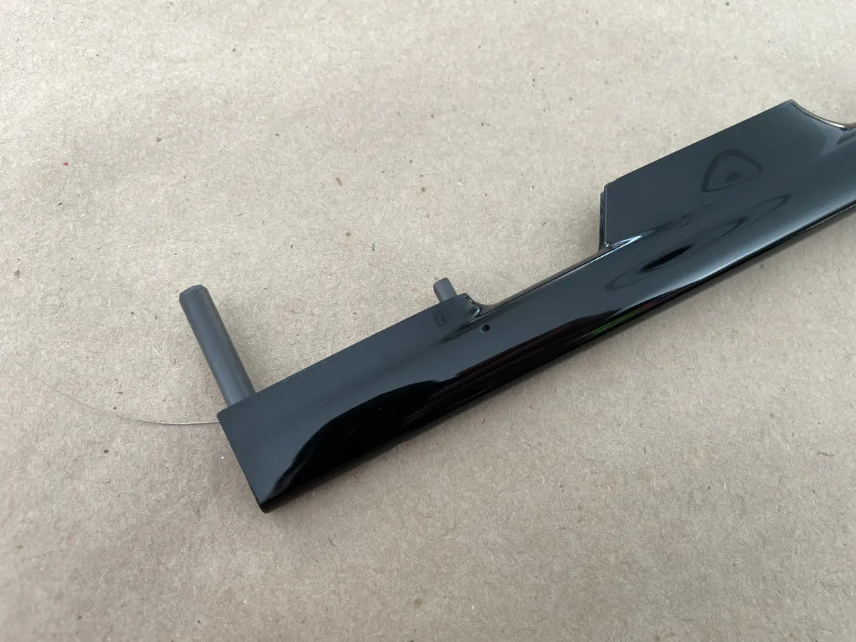
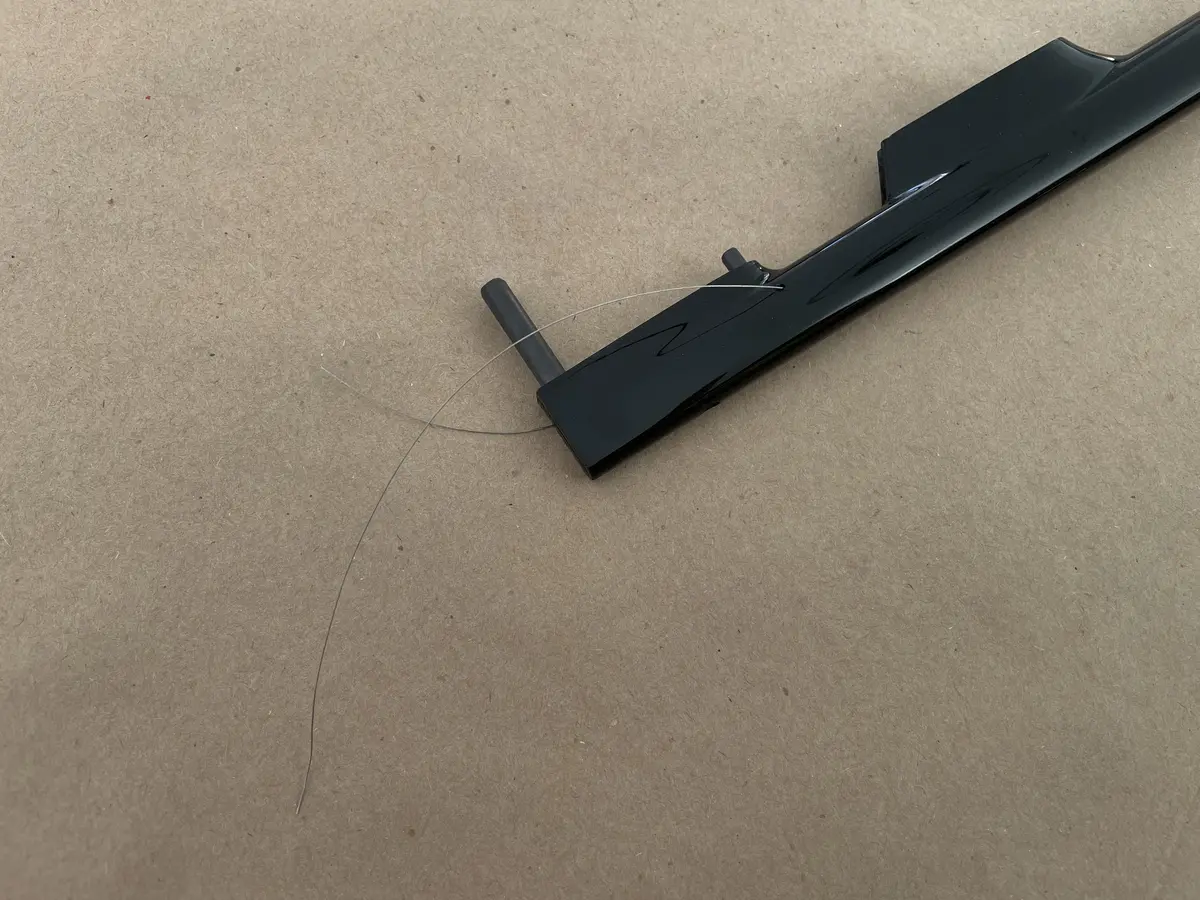
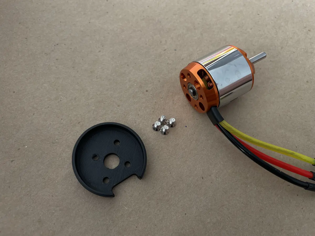
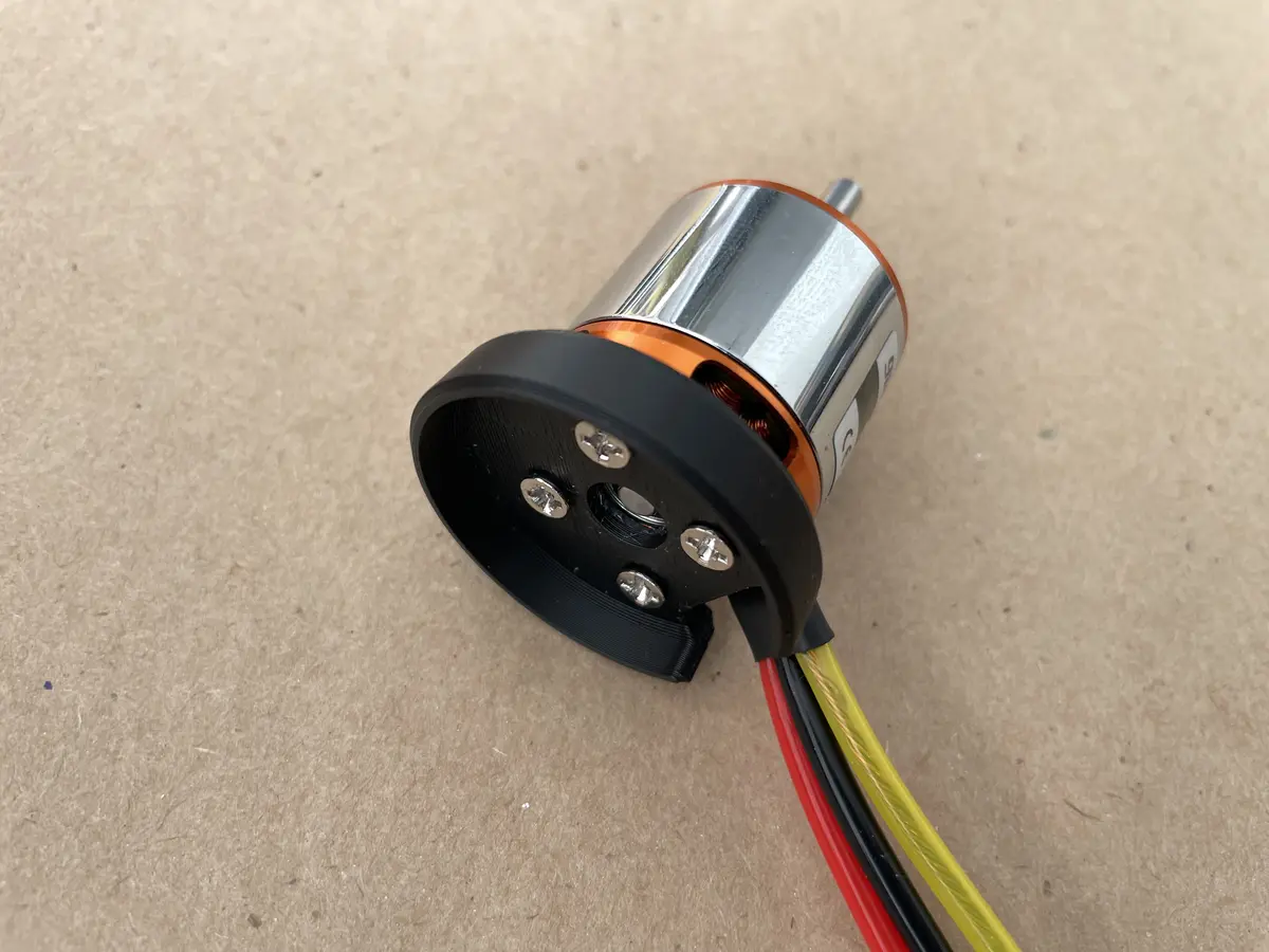
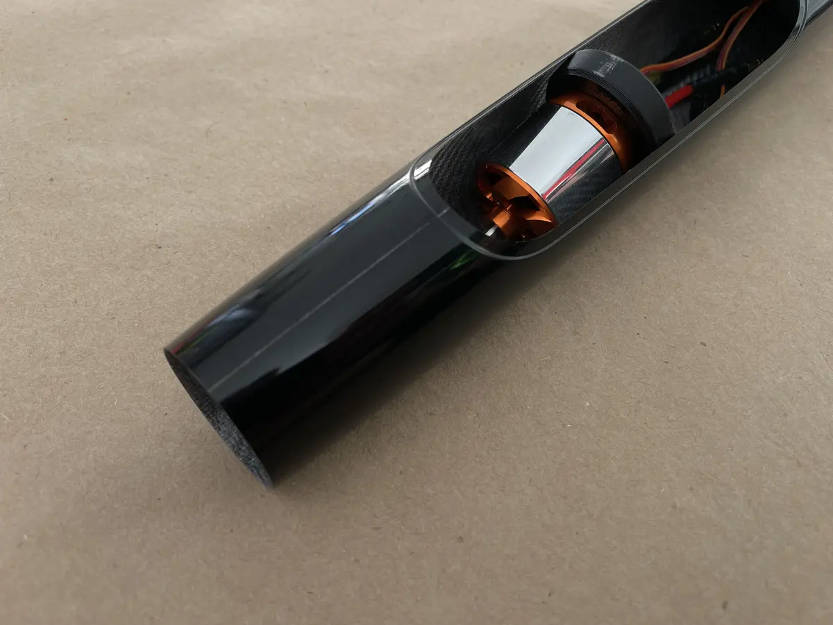
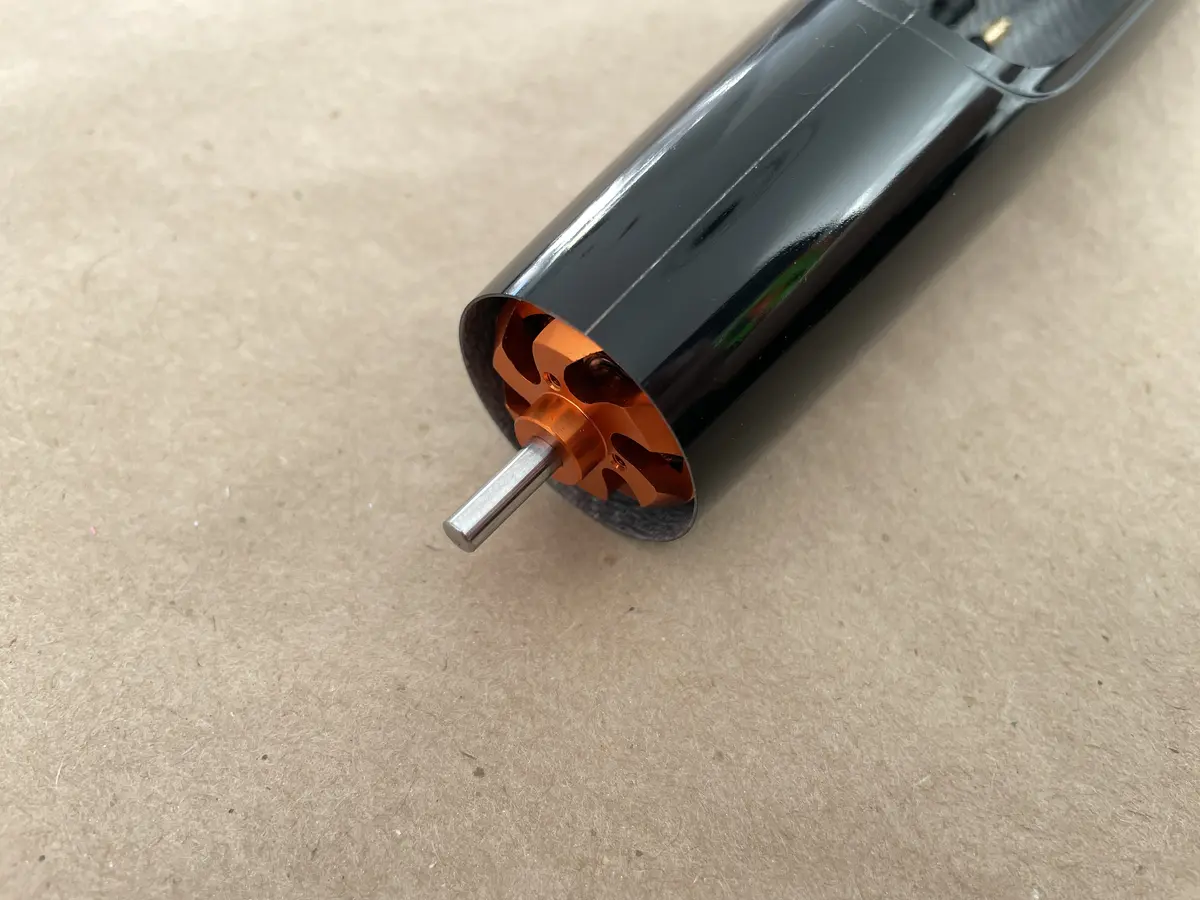
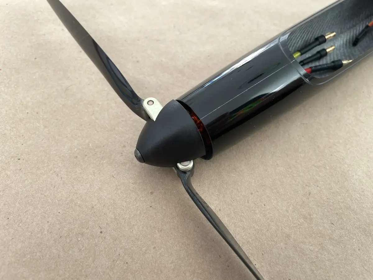
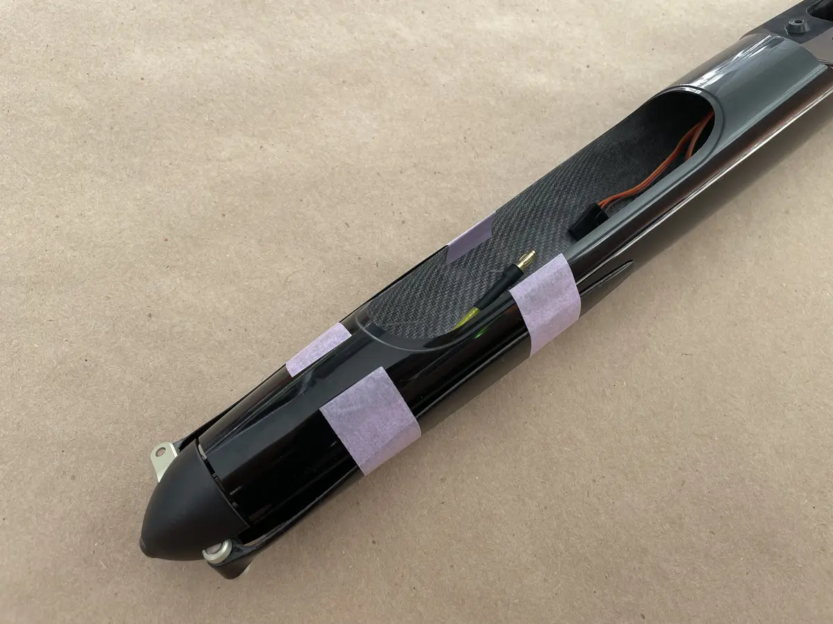
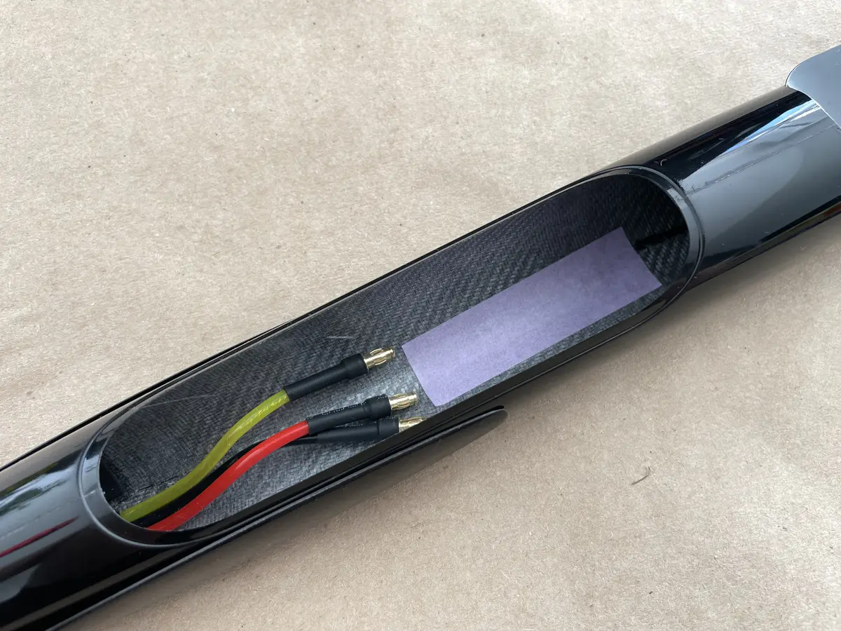
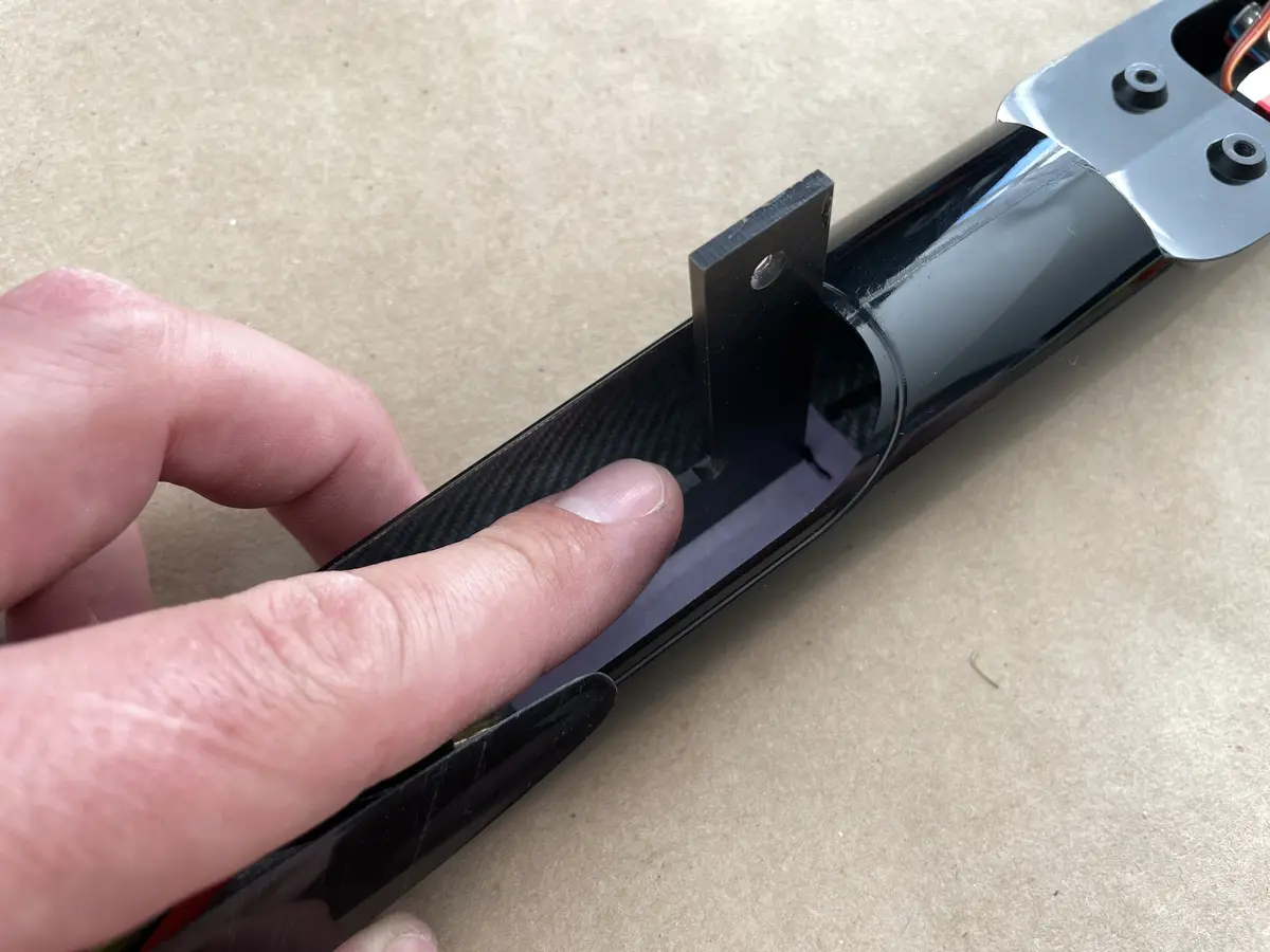
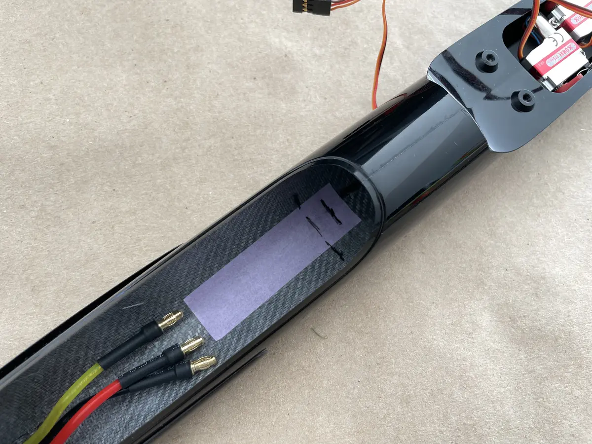
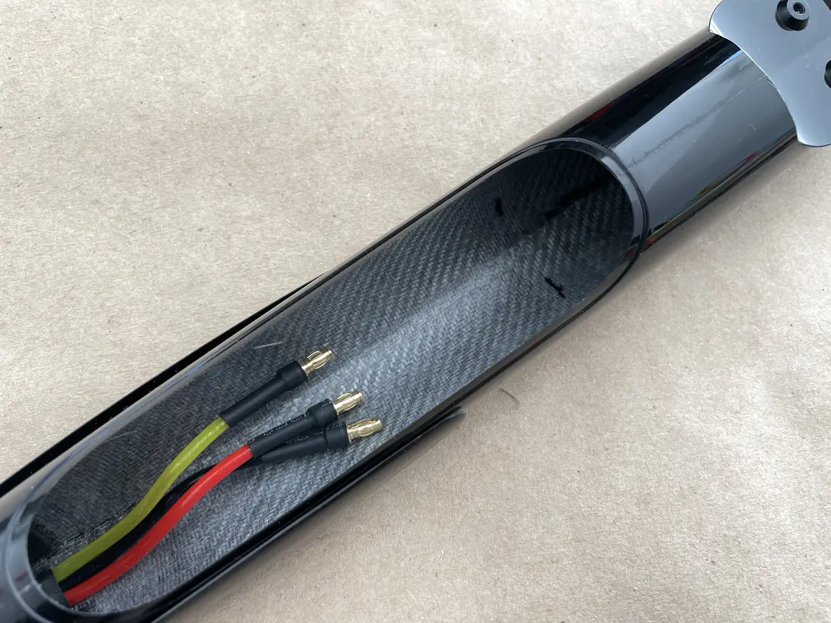
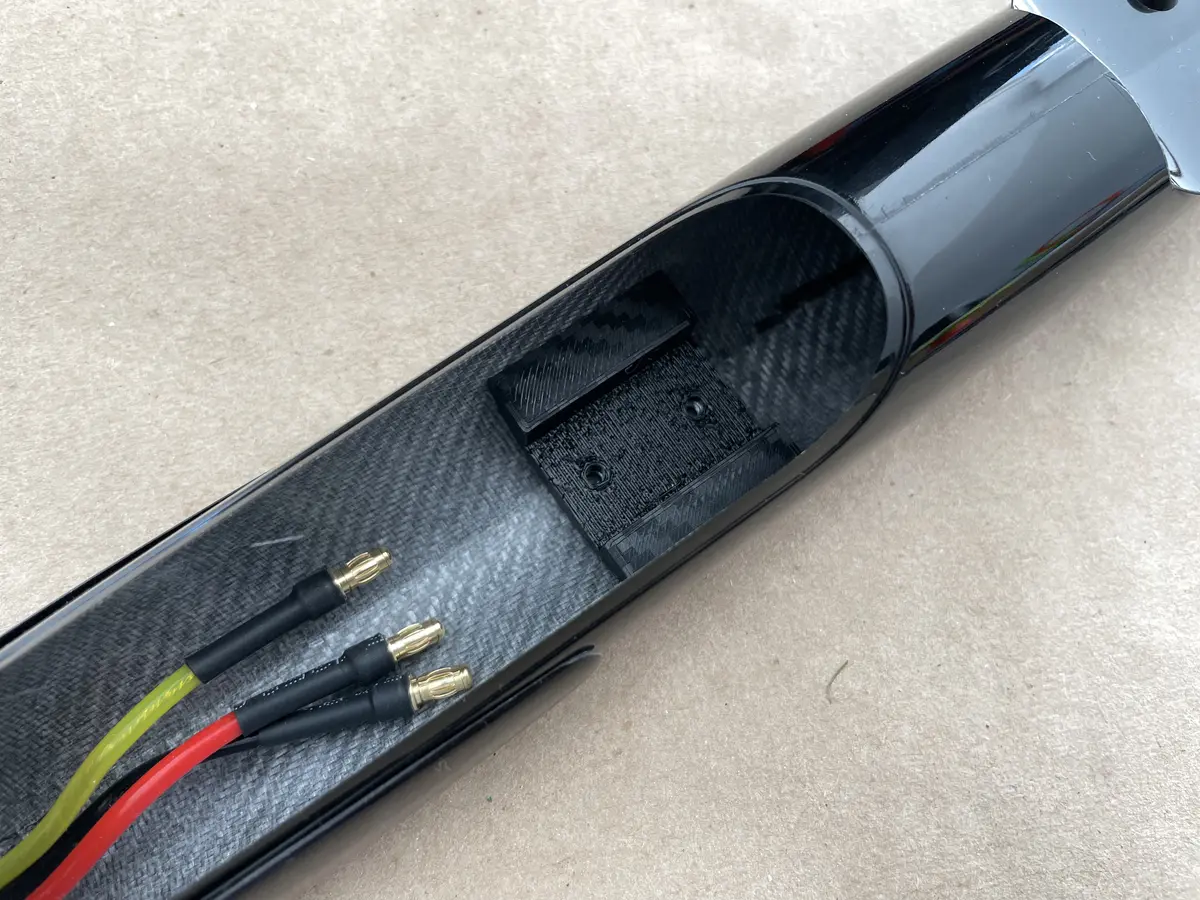
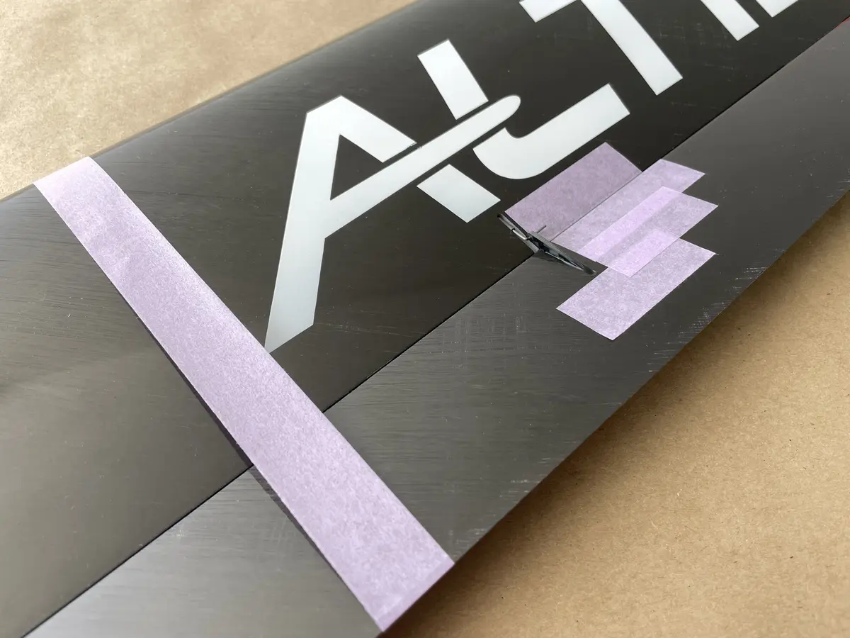
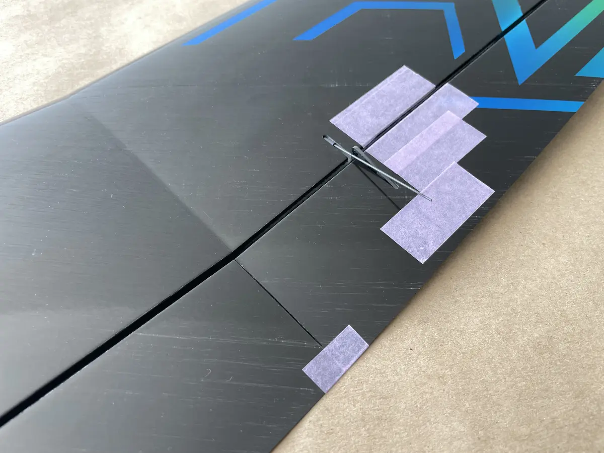
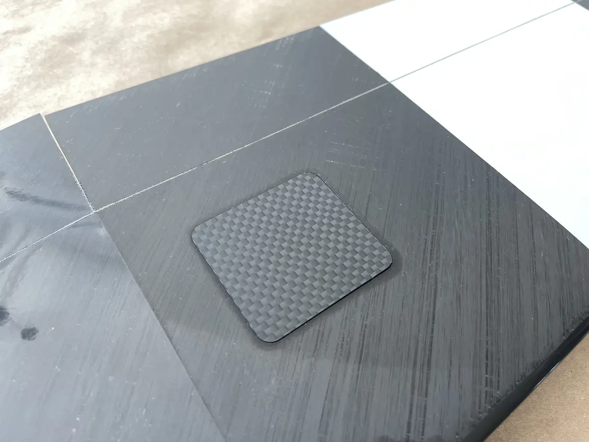
Find the mount in the accessories packDry-fit the assembly inside the fuselage to make sure you have enough room for the servo arms Trim the servo arms and screw the servos onto the frameCenter your servos one by one and install the arms at a 90° angle to the servo casePosition the servo frame inside the fuselage and fix it with medium CATake one half of the supplied cable and thread it through the crimp tube, forming a loopForm a second loop on the “longer” side of a cable by pulling it through the crimp tube once moreTrim your loops like in the picture and crimp the tube. The leftover pigtail should be 100~130mm longInstall the stabilizer in place and make sure it can move all the way down so the elevator can touch the boom Push the cable through the boom and hook the loop you just created to the control hornPush the cable through the crimp tube firstNext, through the control horn, and back through the tubeThen move the Elevator 100% down and secure it with masking tape. The cable loop should be intactMove the elevator servo arm 100% forward with a servo tested or your radioFirmly pull on the cable, crimp the tube, and cut the excess cable. Then fix the crimp with a drop of CAInstall the vertical fin and mark the location of the cable opening. Might be further forward as wellDrill the hole and remove the masking tapePush the other half of the cable through the opening and all the way forward through the boomPush the “servo” side of the wire through the crimp tubeThen, through the servo arm and back through the tubeCrimp the assembly and trim the unneeded cable. Fix with CAFix the fin into the “flying position.” Form a loop through the crimp tube and attach the cable to the respective control hornSet your Rudder servo in a neutral positionPull on the cable, set the Rudder straight, and crimp the tube. Trim the excess and secure the crimp with a drop of CAFind the 3D-printed motor mount supplied with the kitMount your chosen motor to itAssemble the prop & spinnerDrop the motor with the mount into the fuselage Push it to the front to get access to the shaftInstall the prop onto the shaftPosition the spinner and fix it in place with masking tape, leaving ~1mm gap between the spinner and the fuselage. Then fix the mount with CA or epoxyMask the inside of the fuselagePut a mark on the bottom of the pod where the rear end of the opening is projected. Measure 10mm to the front from that mark on the fuselage wallRemove the mask – this is where the rear end of the ballast seddle should be locatedInstall it and fix it with CA or Epoxy.
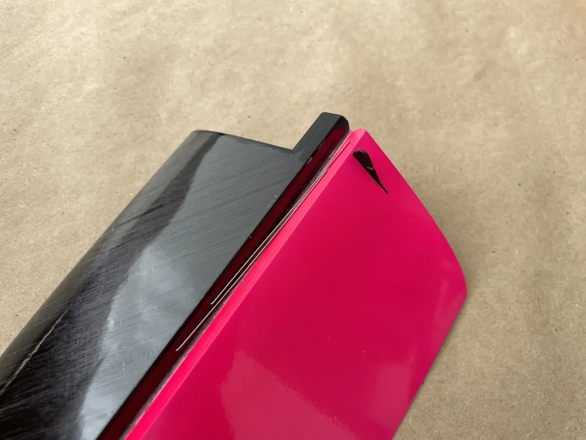
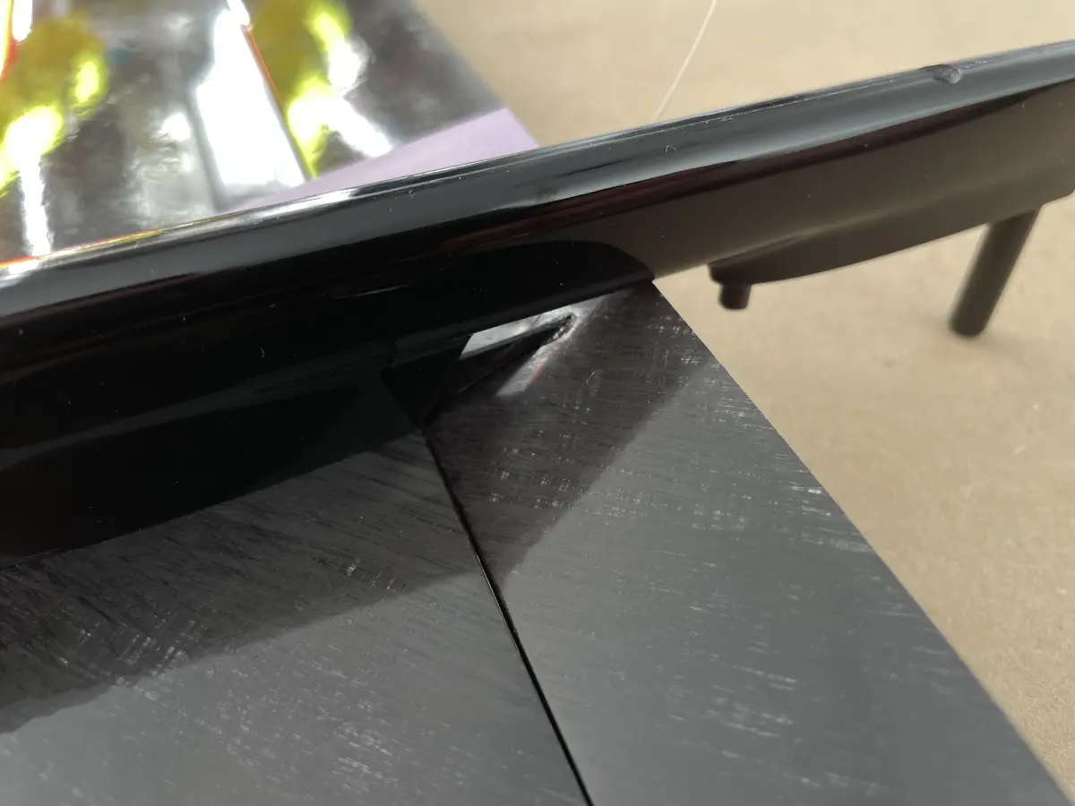
Like some other RC gliders, the Altis F5J does not come with a system to fix the fuselage hatch cover to the fuselage.
So, you need to create it on your own.
There are lots of ways for it, but we strongly recommend making a sticky tape O-Ring.
It’s also strongly recommended to use it for models that have a click-in hatch, like the Joy and the Aerix.
Watch the video below for a step-by-step instruction on how to make it in under 5 minutes.
Part 3. Wings
Prepare your servos – trim the control arms, center the range, and install them 90° to the body. Then, mount on the provided servo framesTake a pushrod wire from the kit and “drill” a control horn hole with it to create a snug fitDo the same with the control horns.Position your servo frames inside the servo bays, and check the slot location on the top side of the wing to matchGlue the servo frames into the bays with CA or EpoxyConnect the servo lead to the harness connector and pack the wires around the servoTemporarily fix the wires with a stripe of masking tapeUse the 2×1 mm tubes provided with the kit to create pushrod channels. Just push it through the foamMake sure it comes out “into” the servo arm for better performanceNext, make the L-bends on one side of the wires and cut the carbon tubes to the sizes as in the picSlide the pushrod into the channel and through the carbon tubeSet the servo to the 100% FLAP UP position – servo arm forwardFix your FLAP in the upright position with masking tape. You’ll need approximately 10mm of UP travel for flapsDry-fit the control horn and mark where the L-bend will beSet the servo arm to 100% backward to release more pushrord to work withBend the pushrod and cut the excess wireSet the servo arm to MAX UP postion once again and hook the control horn on the L-bendFix the FLAP in MAX UP position ~10mm up from the rootSlot in the control horn and fix it with CA or EpoxyThen repeat the process for the aileron, setting the servo in neutral this timeWhen the servo is in neutral, lay your wing flat on a flat surface when making an L-bend and gluing the control horn inOnce done, position the CF tubes so they clear the servo arm, and fix these with a drop of CA on a pushrod wireLastly, install your servo bay covers and fix them permanently with capton tape or similarRepeat for both wings to complete your assembly
Part 4. Radio Setup
Once you connect your servos to the Rx, your first step should be getting the neutrals on your flying surfaces.
It may sound complicated, but on a molded full-house carbon wing, there is a cool trick called the “reflection method.”
Check the video below for details:
Then, please, use the following settings as your baseline for the control throws setup before the first flight. Feel free to adjust these according to your liking.
CG Position
75-80mm from the LE, measured at the root of the wing.
Rudder
+/- 25mm
Elevator
+/- 15mm
Ailerons
+/- 14mm (Ail to Flap: +/- 6mm)
Cruise
Flat bottom of the wing (0mm) or aligned with wing fairing on the fuselage.
Speed
1-3mm up
Thermal 1
3mm down
Thermal Max
8mm down
Brakes
Flaps: 25-30mm down, Ailerons: 15mm down or 7mm up
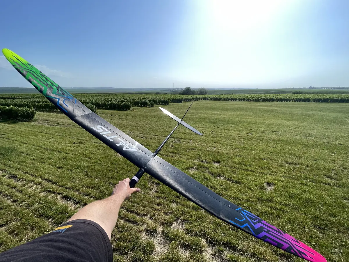
Lastly, choose a calm day for a maiden and have fun!